
Fail-safe distributed access control system

a distributed access control and failure-safe technology, applied in the field of distributed systems, can solve the problems of affecting the performance of the distributed system, slowing down the authorization process, and large number of requests to the component, and achieve the effect of quick, easy and sa

Inactive Publication Date: 2016-06-09
DORMAKABA SCHWEIZ AG
View PDF26 Cites 1 Cited by
  • Summary
  • Abstract
  • Description
  • Claims
  • Application Information

AI Technical Summary

Benefits of technology

This patent describes a distributed system that can verify and predict the behavior of a system and find vulnerabilities or potential attack points. The system includes a policy language component that can execute an authorization process even if there is a failure in communication with another component. The system is more reliable, stable, and safe compared to state-of-the-art systems. Additionally, the system may be faster and more efficient, as it can handle failures quickly and not interrupt the system's functioning. An analysis tool helps to enhance the distributed system and find strengths and weaknesses.

Problems solved by technology

Disadvantages of such distributed systems are a large number of requests to the component that stores the policies.
A large number of requests can degrade the performance of the distributed system and slow down authorization processes.
The distributed system can be impaired or even stall if communication with the component storing the policies is of low quality or is blocked.
Communication of low quality or blocked communication can also lead to undesired grants and denies of the authorization process, i.e. granting instead of denying access and vice versa, for example if an update on authorization information did not reach the PDP in time.
The firmware of a component features a large size and a high complexity.
A distributed system including components with complex firmware is prone to logical inconsistencies and / or programming errors with regard to the functioning of the component and / or of the entire distributed system.
Such distributed systems or their components are difficult to set up, to test and / or to install.
Such distributed systems or their components are also difficult to maintain, to repair and / or to replace.
Such distributed systems or its components are also difficult to update and / or to modify.
Enlarging, updating, customizing or adapting such distributed systems or their components is tedious and time consuming.
Such testing is time consuming, tedious and / or work intensive.
Testing is often done on the spot (i.e. on an installed distributed system in its final configuration and at its final location), which is disadvantageous for different reasons.
For example, testing the distributed system after installing it prolongs the installation time and results in a prolonged unavailability of the distributed system.
Errors are unexpected behavior, undesired behavior and / or malfunctions of the distributed system.
Finding, determining and / or correcting the errors is difficult and time consuming, especially if testing is done on the spot.
Also a modification of the components and / or a modification of the firmware of the components is in most cases difficult to be done on the spot.
Furthermore, the state-of-the-art distributed systems cannot be analytically checked for undesired grants and / or undesired denies due to low quality and / or blocked communication.
In other words, one can neither pose nor answer analysis questions pertaining to the result of an authorization process when communication between the components in the distributed system is impaired and / or blocked.
Such undesired grants and denies often require a specific sequence of failure events to occur in the distributed system.
Therefore, the undesired grants and denies are often missed by testing of the distributed system and furthermore they can remain undetected for a long time during the life-cycle of the distributed system.
Such undesired grants and denies can be dangerous because they can be exploited by an attacker who can intentionally trigger the sequence of failures by disrupting communication channels.

Method used


Image

  • Fail-safe distributed access control system
  • Fail-safe distributed access control system
  • Fail-safe distributed access control system

Examples


Embodiment Construction

[0083]The reference symbols used in the drawings, and their meanings, are listed in summary form in the list of reference symbols. In principle, identical parts are provided with the same reference symbols in the figures.

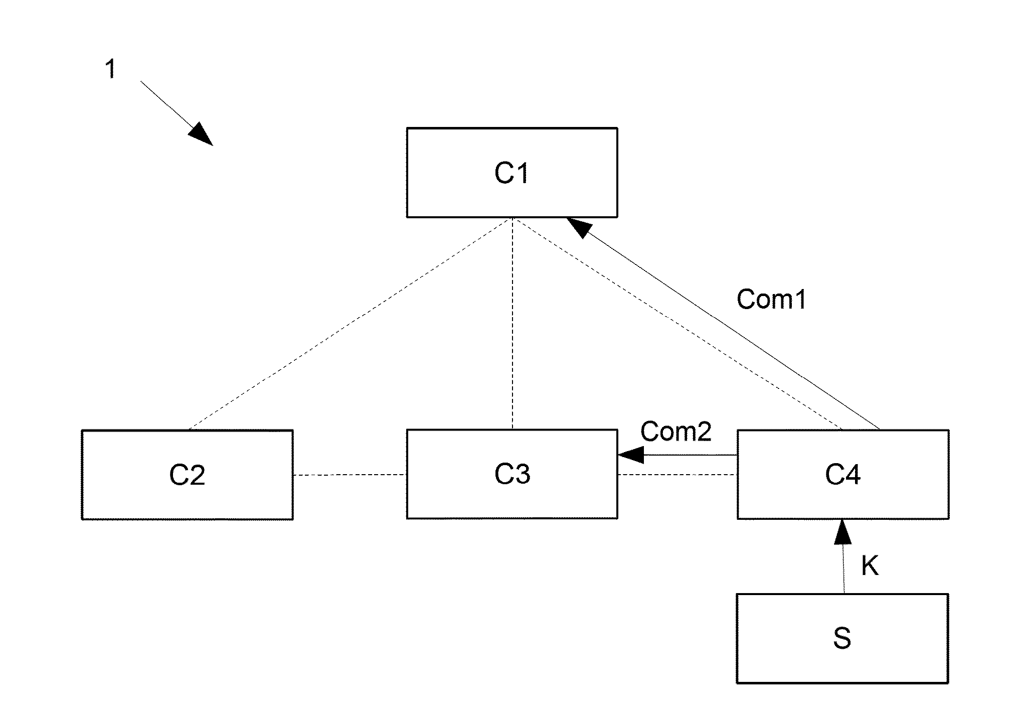
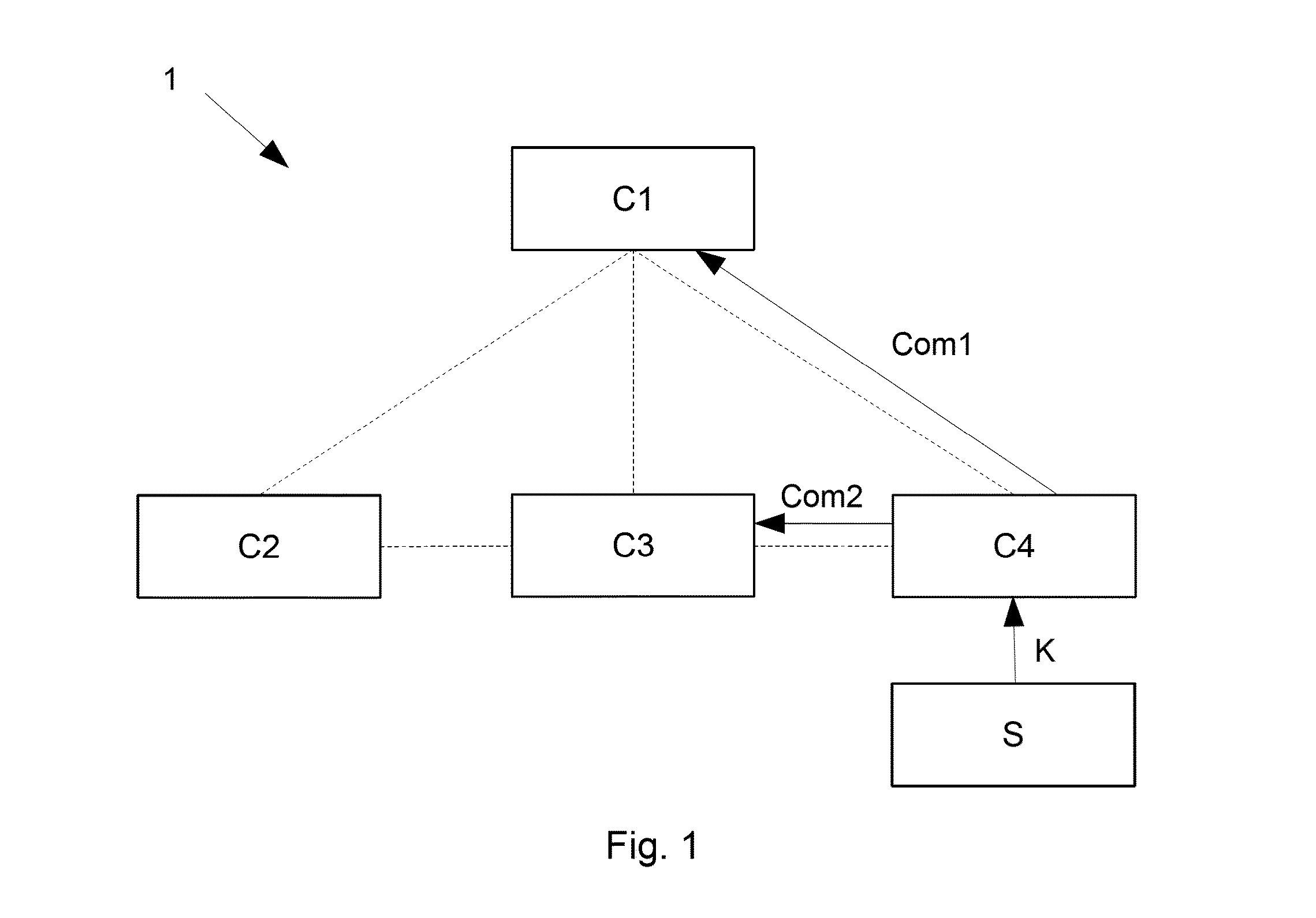
[0084]FIG. 1 schematically shows a distributed system 1 which is a physical access control system. The distributed system 1 includes four components C1-C4. In this example, all four components C1-C4 feature a memory which is capable to store policies. If policies are stored in the respective memories, then the policies are stored in a formal policy language. Communication between components means exchange between components and is represented in FIG. 1 as dashed lines between the four components C1-C4. Communication is in this context always a process in two ways: from one component to another and vice versa. The first component C1 features a central storage for policies, which are stored in a centralized way. The second, third and fourth component C2-C4 are PDPs in...


PUM


Abstract

A distributed system includes two or more components, where at least one of the components is a Policy Decision Point (PDP). The PDP is capable of requesting information from another component of the distributed system, and the PDP is capable of executing an authorization process based on one or more policies defined in a policy language. The policy language includes a communicate command, an execution of which causes the PDP to request information from another component in the distributed system. The policy language also includes a fail operator, which defines handling of failures of the communicate command. An analysis tool for analyzing a result of an authorization process in a Policy Decision Point is also described.

Description

BACKGROUND OF THE INVENTION[0001]1. Field of the Invention[0002]The invention relates to the field of distributed systems including two or more components, where at least one of the components is a Policy Decision Point (PDP). The PDP is capable of requesting information from another component of the distributed system, and the PDP is capable of executing an authorization process based on one or more policies defined in a policy language. The invention also relates to an analysis tool for analyzing a result of an authorization process in a PDP. The invention relates to a distributed system and an analysis tool.[0003]2. Field of the Invention[0004]Distributed systems having a PDP capable of executing an authorization process are widely used in different technical fields. For example, a computer network is a distributed system including separate computers (i.e. components). The computer network may include one computer that is a PDP. The PDP is capable of authorizing a specific user t...

Claims


Application Information

Patent Timeline
Patent Type & Authority Applications(United States)
IPC IPC(8): H04L29/06
CPCH04L63/10H04L63/14H04L63/08H04L67/1034H04L63/20H04L69/40
Inventor BASIN, DAVIDMARINOVIC, SRDJANDASHTI, MOHAMMAD TORABITSANKOV, PETER
Owner DORMAKABA SCHWEIZ AG
Learn More