Shielded Harness and Manufacturing Method Therefor

Active Publication Date: 2016-06-09
YAZAKI CORP
View PDF1 Cites 5 Cited by
  • Summary
  • Abstract
  • Description
  • Claims
  • Application Information

AI Technical Summary

Benefits of technology

The invention provides a shielded harness that can effectively shield high-voltage cables, while also limiting the number of steps and components used during manufacturing.

Problems solved by technology

This causes an increase in the number of steps and the number of components used during manufacturing.

Method used


Image

  • Shielded Harness and Manufacturing Method Therefor
  • Shielded Harness and Manufacturing Method Therefor
  • Shielded Harness and Manufacturing Method Therefor

Examples


Embodiment Construction

[0029]Hereinafter, a preferred embodiment of the present invention will be described with reference to the accompanying drawings. In a description to be given hereinbelow, a shielded harness in the embodiment is an underfloor shielded harness, but the shielded harness is not limited to the underfloor shielded harness, and may be shielded harnesses that are provided at other locations.

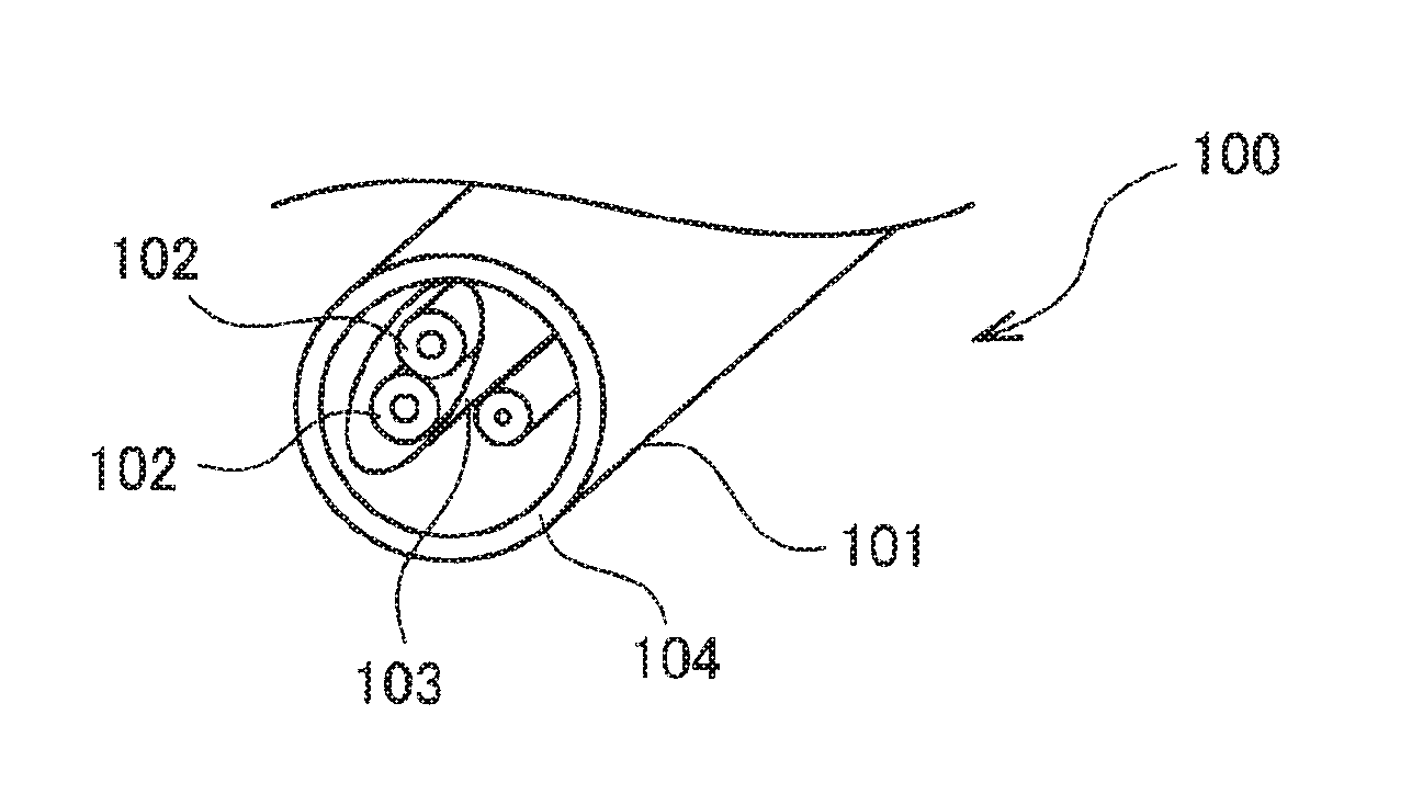
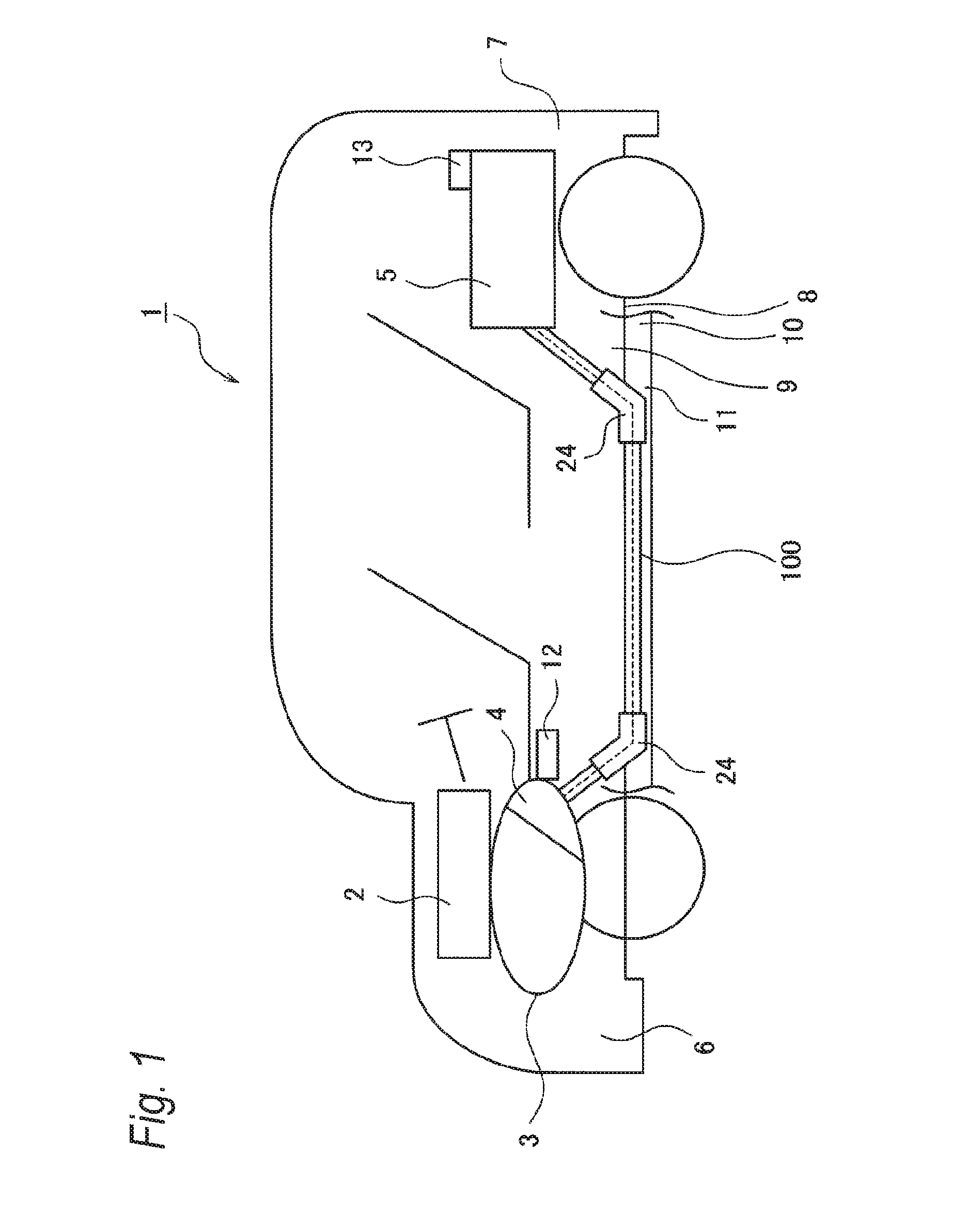
[0030]FIG. 1 is a schematic view illustrating a vehicle in which the underfloor shielded harness in the embodiment of the present invention is routed. As illustrated in FIG. 1, a vehicle 1 is a hybrid vehicle that is driven by two power sources, that is, an engine 2 and a motor 3. Electric power is supplied from a battery 5 to the motor 3 via an inverter 4. The engine 2, the motor 3, and the inverter 4 are mounted on a vehicle-interior front side 6 on which the front wheels and the like are present. The battery 5 is mounted on a vehicle-interior rear side 7 on which the rear wheels and the like are pres...


PUM


Abstract

Disclosed is a shielded harness (100) which includes a low-voltage cable (101) and a high-voltage cable (102) to which a voltage higher than that of the low-voltage cable (101) is applied, and into which the low-voltage and the high-voltage cables (101 and 102) are bundled, the shielded harness (100) including: a cylindrical shield member (103) that covers the circumference of the high-voltage cable (102) to form an gap so as to electromagnetically shield; and a cylindrical protective member (104) that covers the circumference of the shield member (103) and the low-voltage cable (101). The shield member (103) and the protective member (104) are partially bonded or welded together.

Description

TECHNICAL FIELD[0001]The present invention relates to a shielded harness and a manufacturing method therefor.BACKGROUND ART[0002]In recent years, in the automotive industry, the transition from gasoline vehicles to electric vehicles have been examined, and various high-voltage cables have been suggested. It is necessary to ensure the shielding properties of the high-voltage cables. For this reason, the shielding properties of a harness including high-voltage cables are ensured by covering each of the high-voltage cables with a conductive braid, collectively covering a bundle of the high-voltage cables with an insulator using an extrusion molding method, and putting the bundled high-voltage cables into an exterior member such as a corrugated tube (refer to PTL 1).[0003]In a harness disclosed in PTL 1, each of the high-voltage cables has to be covered with a braid. This causes an increase in the number of steps and the number of components used during manufacturing.[0004]As a result, ...

Claims


Application Information

Patent Timeline
IPC IPC(8): H05K9/00H01B13/22B60R16/02
CPCH05K9/0049H01B13/22B60R16/0207B60R16/0215H02G3/0481
Inventor YAMADA, MAKI
Owner YAZAKI CORP
Why Eureka
Try Eureka