[0022]The same reference numerals refer to the same parts throughout the various figures.
DESCRIPTION OF THE CURRENT EMBODIMENT
[0023]An embodiment of the projectile with amorphous plastic tip of the present invention is shown and generally designated by the reference numeral 10.
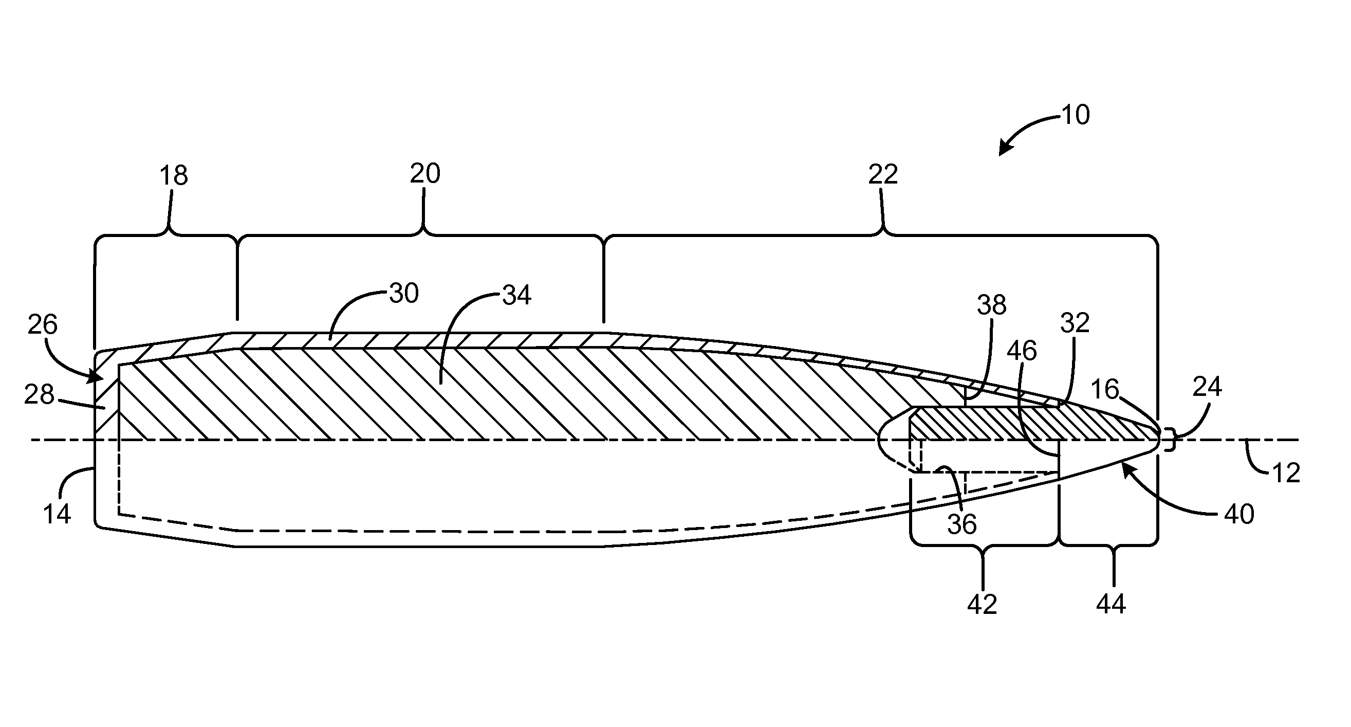
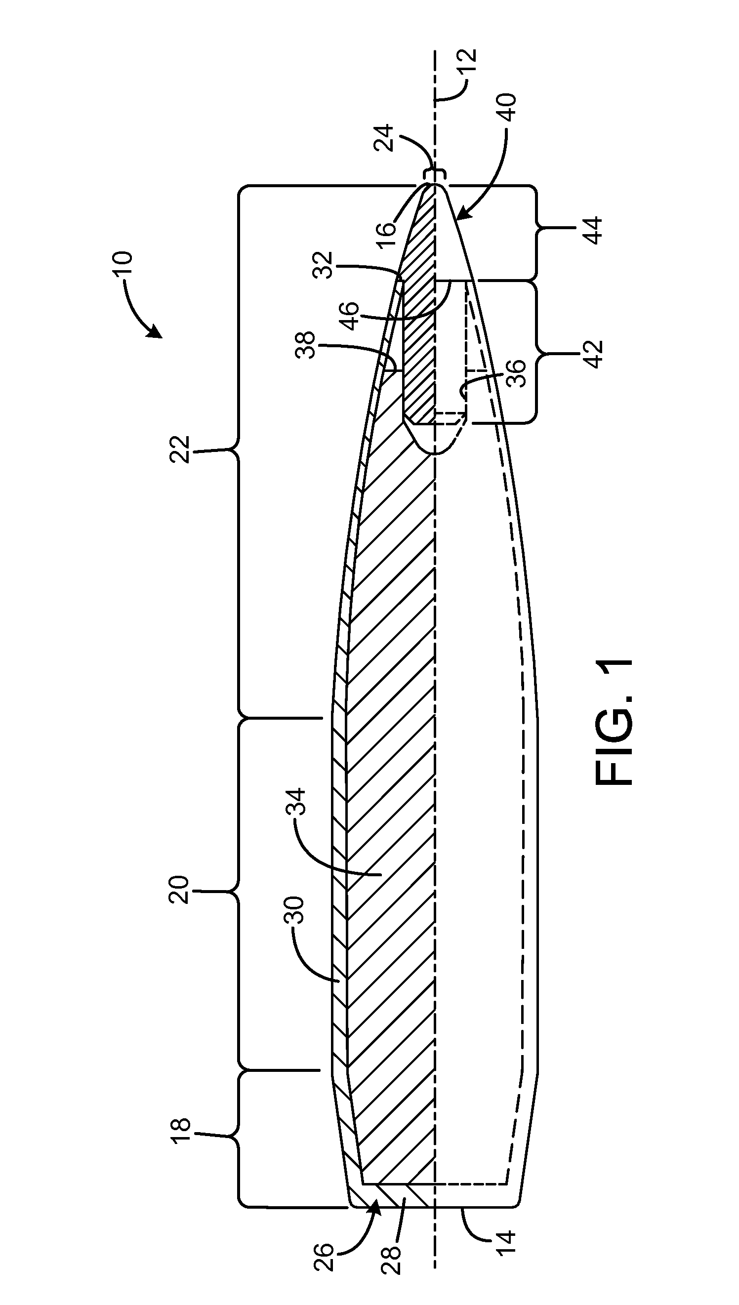
[0024]FIG. 1 illustrates the improved projectile 10 of the present invention. More particularly, the projectile is a generally cylindrical body, symmetrical in rotation about an axis 12, with a rear end 40 and a forward tip 16. The projectile has an exterior surface shaped as follows: a rear portion 18 has a tapered frustoconical “boat tail” surface; a cylindrical intermediate portion 20 continues forward from the rear portion with a straight cylindrical side wall. Continuing, a forward ogive surface portion 22 has a gentle curve toward a meplat portion 24 at the tip. The meplat is a small diameter spherical portion. The ogive has a larger radius (as taken in a plane including the bullet's axis, as illustrated) than the intermediate section's diameter (taken in section across the axis), and also a much larger radius than that of the meplat, as will be quantified below.
[0025]The projectile 10 is formed of a copper jacket 26 having a base portion 28, with side walls 30 extending forward to a rim 32 at a forward position on the ogive section, spaced apart from the meplat. The jacket closely surrounds a lead core 34 that defines a cylindrical cavity 36 in a forward face 38 of the core. The forward face is rearward of the jacket edge 32 in this particular embodiment, and the cavity is concentric with the axis 36.
[0026]The projectile tip is formed by a nose element 40 having a first shank portion 42 and a second tapered portion 44 formed as a unitary body of the same material. The shank portion is a cylindrical portion having a diameter equal to the diameter of the jacket rim, and which is closely received in the cavity of the core. The second portion has a larger diameter than the shank at its base adjacent to the shank. The base of the second portion forms a shoulder 46, and tapers to form the tip. The jacket rim tightly grips the base of the shank at the shoulder, to secure the nose into the projectile body.
[0027]The nose element is formed of suitable amorphous plastic resins, such as Polysulphone (PSF), Polyetherimide (PEI), and Polyphenylsulphone (PPSU), which exhibit high glass transition point temperatures greater than or equal to 185° C., and high molding temperature melt points, above 330° C. Specifically, PSF has a glass transition point of 185° C., and PEI and PPSU are progressively higher, and therefore even more suitable for use in the current invention, with glass transition points of 220° C. and 225° C., respectively. In comparison, the best performing crystalline polymer used in conventional nose elements is nylon 6-6, which has a glass transition point of only 50° C. With these amorphous polymers, the velocities at which tip aerodynamic heating deformation takes place for a polymer tipped projectile can be extended from 2,400 fps associated with conventional crystalline polymer tips up into the 3,100 to 3,200 fps range of velocities. Amorphous polymers are ideal to solve this problem because of their combination of a high glass transition temperature along with the absence of a discrete melt point. Amorphous polymers typically begin to melt at temperatures between 350 to 425° C., depending on the polymer and the conditions. These polymers will withstand very high temperatures compared to conventional crystalline polymers, and only soften without melting and completely losing their shape.
[0028]Up to this point, these types of high temperature amorphous polymers have not been used for small arms projectile tips because they are a considerably more expensive polymer resin, require more handling and preparation prior to molding, and require considerably more effort to mold. As a result, parts produced from these types of polymer resins are more expensive than conventional crystalline polymer projectile tips. High temperature amorphous polymers require drying prior to molding, which the currently used crystalline polymers do not. Amorphous polymers also require specially designed molds that require heated plastic runner systems to preheat the resin prior to molding. These “hot runner” systems run at temperatures of up to 200° C. The “hot runner” systems are not required to mold crystalline polymer resins.
[0029]Despite these higher temperature and more complex equipment and procedural requirements for fabrication, use of high temperature amorphous polymers is by far a superior solution to the problem of crystalline polymer projectile tips melting during long-range projectile flight at high speeds. The use of metal tips has been largely replaced by polymers because of the very high level of manufacturing difficulty and cost associated with small metal tips. In addition, metal tips cannot be formed into the shapes required for mass production of small arms projectiles without the cost becoming so high that the tip is more expensive than the rest of the projectile.
TABLE 1 Hornady ® 30 Caliber 155 Amax Velocity vs. Distance 30 155 Amax - Retained velocity PEI Delrin ® Range (yds.) Velocity (fps) Velocity (fps) 0 2895 2895 100 2723 2711 200 2543 2527 300 2367 2346 400 2196 2168 500 2030 1996 600 1868 1830 700 1712 1669 800 1561 1515 900 1413 1369 1000 1272 1228 Wind drift 8.8 9.3 @ 1000 yds. (minute of angle) Elevation @ 31.1 32.1 1000 yds. (minute of angle)
[0030]Table 1 shows the results of experimentation providing the retained velocity vs. distance for Hornady® 30 caliber 155 Amax bullets with different tip material compositions. Table 1 illustrates the downrange ballistic differences for the .30 caliber 155 grain projectiles used to generate the drag coefficient data in FIG. 4. Velocity distance data is taken directly from Doppler radar, and the wind drift and elevation values are calculated using the FIG. 4 Doppler radar drag data. The amorphous polymer-tipped bullet of the current invention exits the muzzle of the rifle with identical retained velocity as the conventional Delrin® polymer-tipped bullet. However, at a range of 100 yards, the amorphous polymer-tipped bullet of the current invention already shows a higher retained velocity of 12 fps relative to Delrin®. As the range increases, the retained velocity of the amorphous polymer-tipped bullet of the current invention increases compared to the retained velocity of Delrin®. At 800 yards, the amorphous polymer-tipped bullet of the current invention has a retained velocity of 46 fps compared to Delrin®. The retained velocity of the amorphous polymer-tipped bullet of the current invention continues to compare favorably to the retained velocity of the Delrin®-tipped bullet at 900 and 1,000 yards, with a difference of 44 fps.
[0031]While a current embodiment of a projectile with amorphous plastic tip has been described in detail, it should be apparent that modifications and variations thereto are possible, all of which fall within the true spirit and scope of the invention. With respect to the above description then, it is to be realized that the optimum dimensional relationships for the parts of the invention, to include variations in size, materials, shape, form, function and manner of operation, assembly and use, are deemed readily apparent and obvious to one skilled in the art, and all equivalent relationships to those illustrated in the drawings and described in the specification are intended to be encompassed by the present invention.
[0032]Therefore, the foregoing is considered as illustrative only of the principles of the invention. Further, since numerous modifications and changes will readily occur to those skilled in the art, it is not desired to limit the invention to the exact construction and operation shown and described, and accordingly, all suitable modifications and equivalents may be resorted to, falling within the scope of the invention.