Eureka AIR delivers breakthrough ideas for toughest innovation challenges, trusted by R&D personnel around the world.

Dynamic virtual fencing for a hazardous environment

a technology for hazardous environments and fencing, applied in the direction of alarms, process and machine control, instruments, etc., can solve the problems of high possibility of occurrence of hazard from boilers, the impact of hazard, and the possibility of detection of potential hazard from boilers, so as to achieve the effect of safety of personnel

Active Publication Date: 2016-06-16
SIEMENS AG
View PDF16 Cites 33 Cited by
  • Summary
  • Abstract
  • Description
  • Claims
  • Application Information

AI Technical Summary

Benefits of technology

The patent describes a method for automatically generating dynamic virtual fences to detect and prevent potential hazards in a hazardous environment. The method involves detecting a potential hazard associated with a field object, such as a crane or a machining tool, and determining the operational status of the field object based on its risk factors. The method then generates a dynamic virtual fence around the location of the field object on a map of the hazardous environment based on its area and shape and the value of a risk factor. This virtual fence helps to accurately define hazardous zones and provides safety for personnel and other assets in the hazardous environment.

Problems solved by technology

The hazardous environment is an environment such as manufacturing plant, processing plant, mines, etc. that is prone to hazards that arise due to high pressure, high temperature, high voltage, high level, toxic fumes, movement of heavy objects, hazardous materials and so on.
However, if the boiler is operational, then there is a high possibility of occurrence of the hazard from the boiler.
Thus, the possibility of a potential hazard from the boiler may be detected based on operational status of the boiler.
The risk factor is an amount of impact of hazard associated with the potential hazard.
For example, if the temperature of the steam of the boiler increases, the amount of impact associated with the potential hazard may also be severe.

Method used


Image

  • Dynamic virtual fencing for a hazardous environment
  • Dynamic virtual fencing for a hazardous environment
  • Dynamic virtual fencing for a hazardous environment

Examples


Embodiment Construction

[0029]Various embodiments are described with reference to the drawings, where like reference numerals are used to refer the drawings, and like reference numerals are used to refer to like elements throughout. In the following description, for the purpose of explanation, numerous specific details are set forth in order to provide thorough understanding of one or more embodiments. It may be evident that such embodiments may be practiced without these specific details.

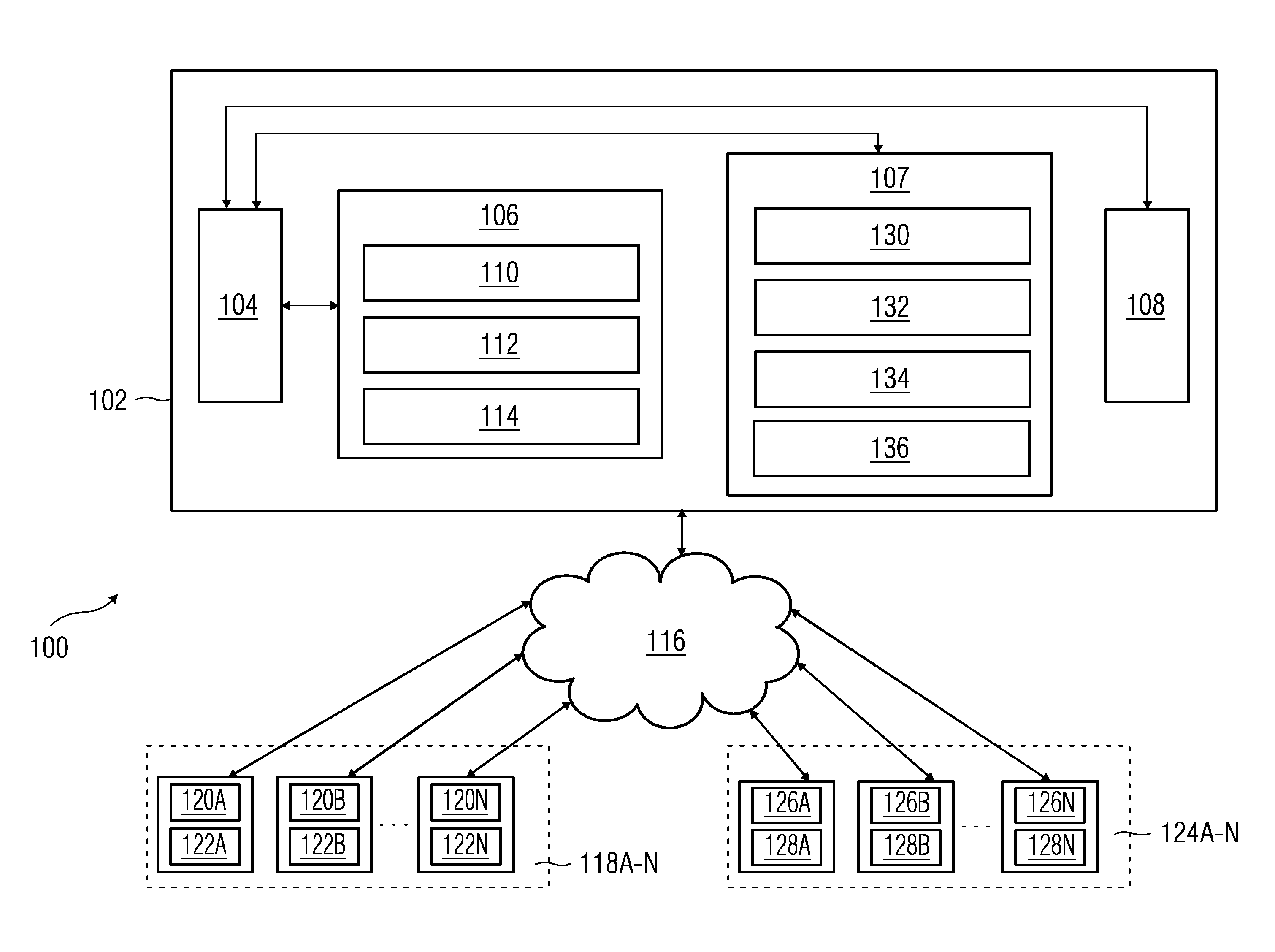
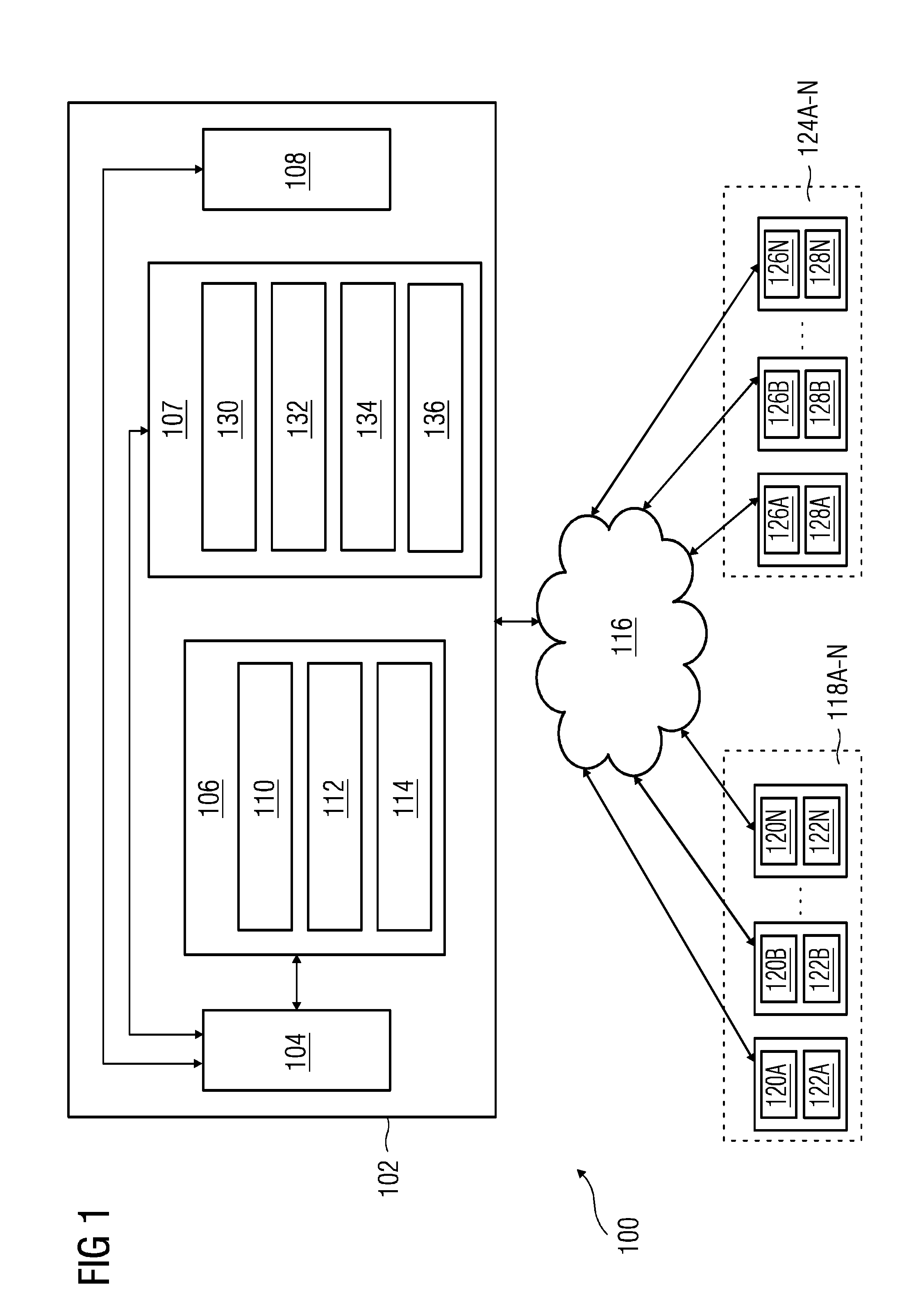
[0030]FIG. 1 illustrates a block diagram of a dynamic virtual fencing system 100 deployed in a hazardous environment according to an embodiment. The hazardous environment may be an industrial setting such as a manufacturing plant, a mining environment, or any other environment that involves risks from hazards. The dynamic virtual fencing system 100 includes a server 102, a plurality of field objects 118A-N deployed in the hazardous environment, and a plurality of mobile devices 124A-N associated with personnel in the haza...


PUM


Abstract

A method and system for automatically generating dynamic virtual fences in a hazardous environment are provided. The method includes detecting a potential hazard associated with a field object in the hazardous environment. The method further includes determining a value of a risk factor of the potential hazard and area and shape of a dynamic virtual fence based on values of real-time operational parameters associated with the field object. The method includes automatically representing the dynamic virtual fence around a location of the field object on a map of the hazardous environment based on the determined area and shape and the value of the risk factor such that the dynamic virtual fence represents a hazardous zone in the hazardous environment.

Description

[0001]This application claims the benefit of EP 14198013.6, filed on Dec. 15, 2014, which is hereby incorporated by reference in its entirety.BACKGROUND[0002]The present embodiments relate to the field of fencing for a hazardous environment.[0003]A hazard is a situation that poses a level of threat to life, property and environment. Most hazards are dormant or potential with a theoretical risk of harm. However, once a hazard becomes active, the hazard may create an emergency situation. Hazard may occur in manufacturing plants, mining environment, and process plants. An environment where a hazard is prone to occur is termed as ‘hazardous environment’. For example, hazard may arise from field objects in the hazardous environment such as boiler, furnace, X-ray devices, slopes in mines, vehicles, toxic fumes and poisonous materials. In the hazardous environment, there may be a plurality of areas or zones that are likely to be affected when the hazard occurs. These areas or zones are kno...

Claims


Application Information

Patent Timeline
IPC IPC(8): G08B21/02
CPCG08B21/02G08B21/0261G05B9/02
Inventor DAS, SAPTARSHIDAS, SIDDHARTHRAGUNATHAN, KARTHIK
Owner SIEMENS AG
Why Eureka
Eureka Blog
Learn More