
Vertical FET Having Reduced On-Resistance

Active Publication Date: 2016-06-16
INFINEON TECH AMERICAS
View PDF1 Cites 5 Cited by
  • Summary
  • Abstract
  • Description
  • Claims
  • Application Information

AI Technical Summary

Benefits of technology

The present patent is about a special type of transistor that has low resistance. The text describes the technical effects of this new technology.

Problems solved by technology

However, conventional strategies for reducing trench MOSFET size may undesirably tend to increase the Rdson of those devices.

Method used


Image

  • Vertical FET Having Reduced On-Resistance
  • Vertical FET Having Reduced On-Resistance
  • Vertical FET Having Reduced On-Resistance

Examples


Embodiment Construction

[0011]The following description contains specific information pertaining to implementations in the present disclosure. One skilled in the art will recognize that the present disclosure may be implemented in a manner different from that specifically discussed herein. The drawings in the present application and their accompanying detailed description are directed to merely exemplary implementations. Unless noted otherwise, like or corresponding elements among the figures may be indicated by like or corresponding reference numerals. Moreover, the drawings and illustrations in the present application are generally not to scale, and are not intended to correspond to actual relative dimensions.

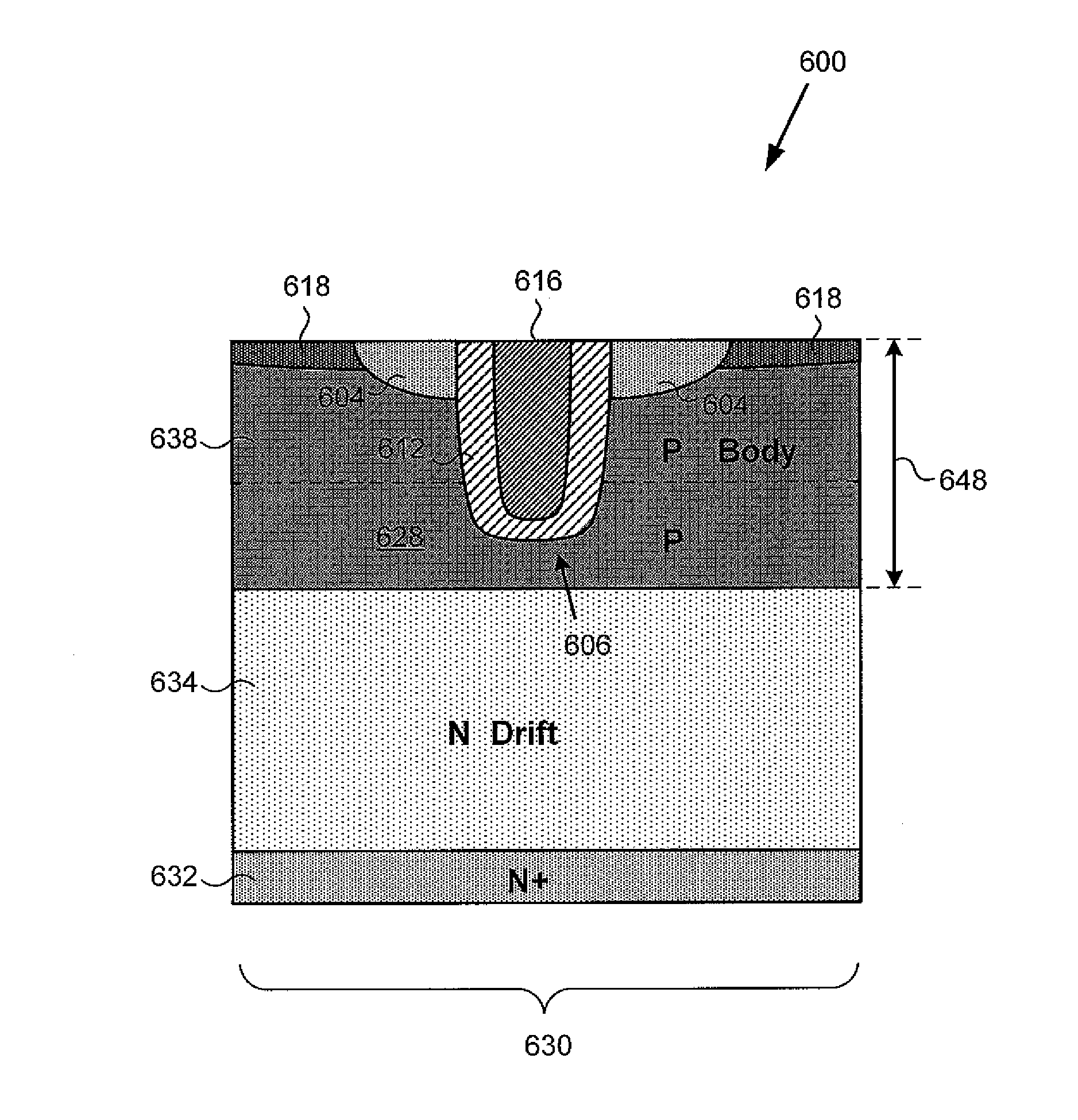
[0012]As stated above, group IV power transistors, such as silicon based trench type field-effect transistors (trench FETs) are used in a variety of applications. For example, silicon based trench metal-oxide-semiconductor FETs (trench MOSFETs) may be used to implement a power converter, such as a s...


PUM


Abstract

In one implementation, a vertical field-effect transistor (FET) includes a substrate having a drift region situated over a drain, a body region situated over the drift region and having source diffusions formed therein, a gate trench extending through the body region, and channel regions adjacent the gate trench. The channel regions are spaced apart along the gate trench by respective deep body implants. Each of the deep body implants is situated approximately under at least one of the source diffusions, and has a depth greater than a depth of the gate trench.

Description

[0001]The present application claims the benefit of and priority to a provisional application entitled “Low Voltage MOSFET Design with Three Dimensional Depletion,” Ser. No. 62 / 092,176 filed on Dec. 15, 2014. The disclosure in this provisional application is hereby incorporated fully by reference into the present application.BACKGROUNDBackground Art[0002]Group IV power transistors, such as silicon based trench type field-effect transistors (trench FETs) are used in a variety of applications. For example, silicon based trench metal-oxide-semiconductor FETs (trench MOSFETs) may be used to implement a power converter, such as a synchronous rectifier, or a direct current (DC) to DC power converter.[0003]For many trench FET applications, it is desirable to substantially minimize the on-resistance (Rdson) of the transistor. In addition, as the electronic devices and systems utilizing power MOSFETs are continually reduced in size, there is a corresponding need to reduce the size of the MOS...

Claims


Application Information

Patent Timeline
IPC IPC(8): H01L29/78H01L29/08H01L29/10
CPCH01L29/7813H01L29/1095H01L29/0882H01L29/086H01L29/1045H01L29/1033H01L29/66734H01L29/0696H01L29/16
Inventor NAIK, HARSHHENSON, TIMOTHY D.RANJAN, NIRAJ
Owner INFINEON TECH AMERICAS
Features
  • Generate Ideas
  • Intellectual Property
  • Life Sciences
  • Materials
  • Tech Scout
  • Unparalleled Data Quality
  • Higher Quality Content
  • 60% Fewer Hallucinations
Learn More