Method for controlling wind turbines

a technology of wind turbines and wind power generators, applied in the direction of electric generator control, machines/engines, mechanical equipment, etc., can solve the problems of not necessarily definite correlations, not at all, etc., and achieve the effect of increasing capacity and adding to the grid's stability

Active Publication Date: 2016-06-16
WOBBEN PROPERTIES GMBH
View PDF6 Cites 8 Cited by
  • Summary
  • Abstract
  • Description
  • Claims
  • Application Information

AI Technical Summary

Benefits of technology

[0013]Preferably, it is thus also proposed to transmit the predicted reactive power as a forecast value to a grid control center that controls the electrical supply grid. In other words: the grid operator is informed about the reactive power that is to be fed in shortly by the wind turbine or wind farm. The grid operator, i.e., the grid control center, can thus better adapt to the situation.
[0015]Moreover, the storm-related reduction in active power can result in that the feed-in units of the wind turbines or wind farm have more capacity available for feeding reactive power due to the reduced active power. This effect is also used in accordance with one or more embodiments of the invention, and it is thus proposed to feed even more reactive power than active power into the grid. This way, one can at least influence the voltage levels in the grid, and the grid operator can respond to such influence.
[0016]According to one embodiment, it is proposed to predict the predicted reactive power for a forecast period. As regards such forecast period, it is now proposed for the wind turbines or wind farm to actually feed in the predicted reactive power, even if the wind speed actually reached should be different from the forecast wind speed. This way, a reliable value is created by the calculation and, in particular, transmission of the predicted reactive power. Others, in particular the grid operator, cannot only respond to, but even rely on that value, which will add to the grid's stability.
[0019]This also avoids an unnecessary calculation and possibly unnecessary transmission in less critical situations. This also makes it possible to avoid any commitment to a predicted reactive power if the wind speed is smaller than in storm situations. Unless a storm has come up, one can often expect less strongly and less spontaneously fluctuating wind speeds, especially in case of a wind farm where slight fluctuations disperse evenly across the wind farm and are less noticeable during feeding. Therefore, an overall more stable situation can be expected at such lower wind speeds, which can do without a reactive power prediction and can instead gear the feeding more precisely towards the grid's current needs, in particular towards the current grid conditions. If no reactive power has been predicted, reactive power can still be fed in, e.g., based on the current grid conditions.
[0021]Preferably, the information provided by other wind turbines and / or other wind farms is used to prepare the wind forecast. One may also use the information provided by well-known meteorological services, in particular information on high and low pressure areas and corresponding large-scale general weather situations and airflows. It is, however, advantageous to use the information of at least one other wind turbine and / or wind farm, since wind turbines and wind farms may be connected through an information system, in particular through the so-called SCADA system. This makes it possible to set up a networked system that is, or may be, based on comparable weather information. Measuring the wind speed may, in particular, depend on numerous factors, especially on the sensor and height at which measuring is performed. If the wind turbine measures the wind speed, for example, with its aerodynamic rotor, such wind speed measurement is based on a very high measuring height, which nowadays may regularly exceed 100 meters, and it is based on a strongly homogenized parameter, since the aerodynamic rotor is comparatively inert—at least compared to a common anemometer that over-sweeps a large surface. By using the wind performance data of other wind turbines or wind farms, one ultimately takes as a basis the very wind performance values that become relevant and effective later on at the respective wind turbine.

Problems solved by technology

However, such correlations that are to be expected are not necessarily definite, and they are, in particular, hardly—or not at all—foreseeable for devices or installations other than wind turbines, for example for a grid operator.

Method used


Image

  • Method for controlling wind turbines
  • Method for controlling wind turbines
  • Method for controlling wind turbines

Examples


Embodiment Construction

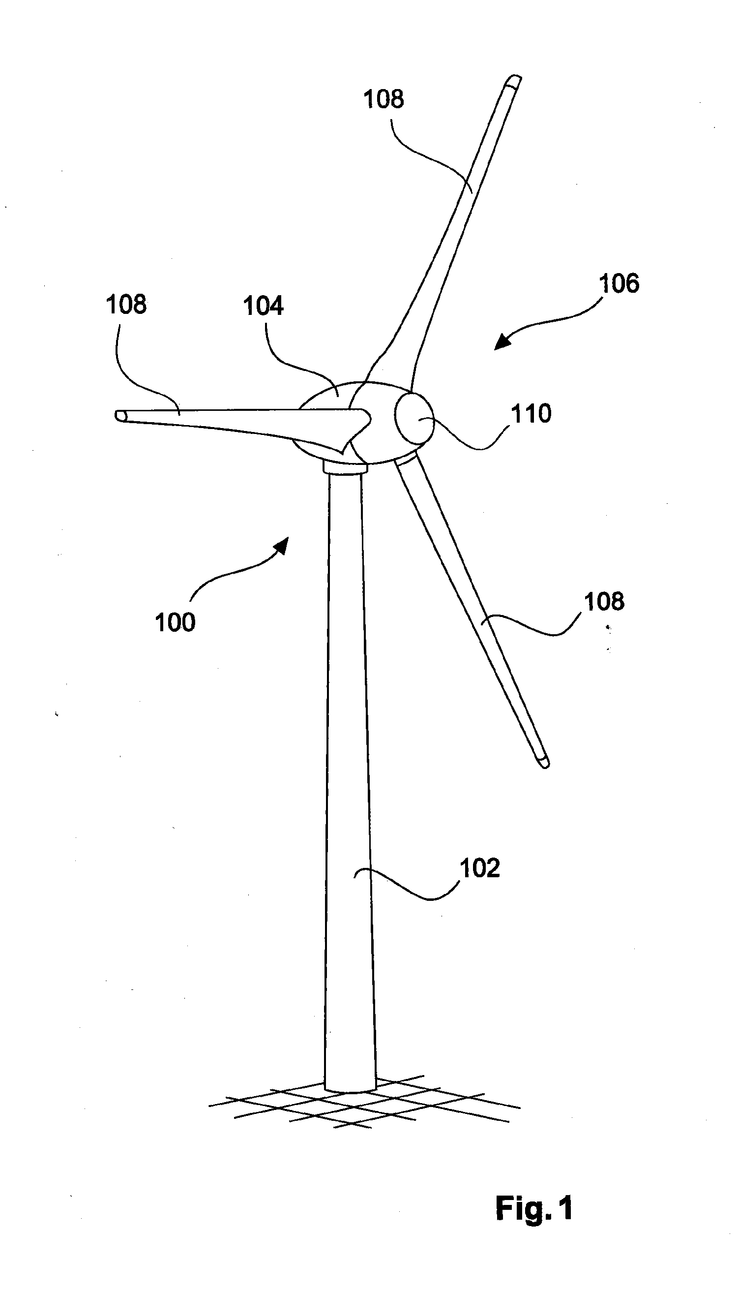
[0034]FIG. 1 shows a wind turbine 100 with a tower 102 and nacelle 104. A rotor 106 with three rotor blades 108 and a spinner 110 is located on the nacelle 104. When in operation, the rotor 106 is brought to a rotating movement by the wind and thereby drives a generator in the nacelle 104.

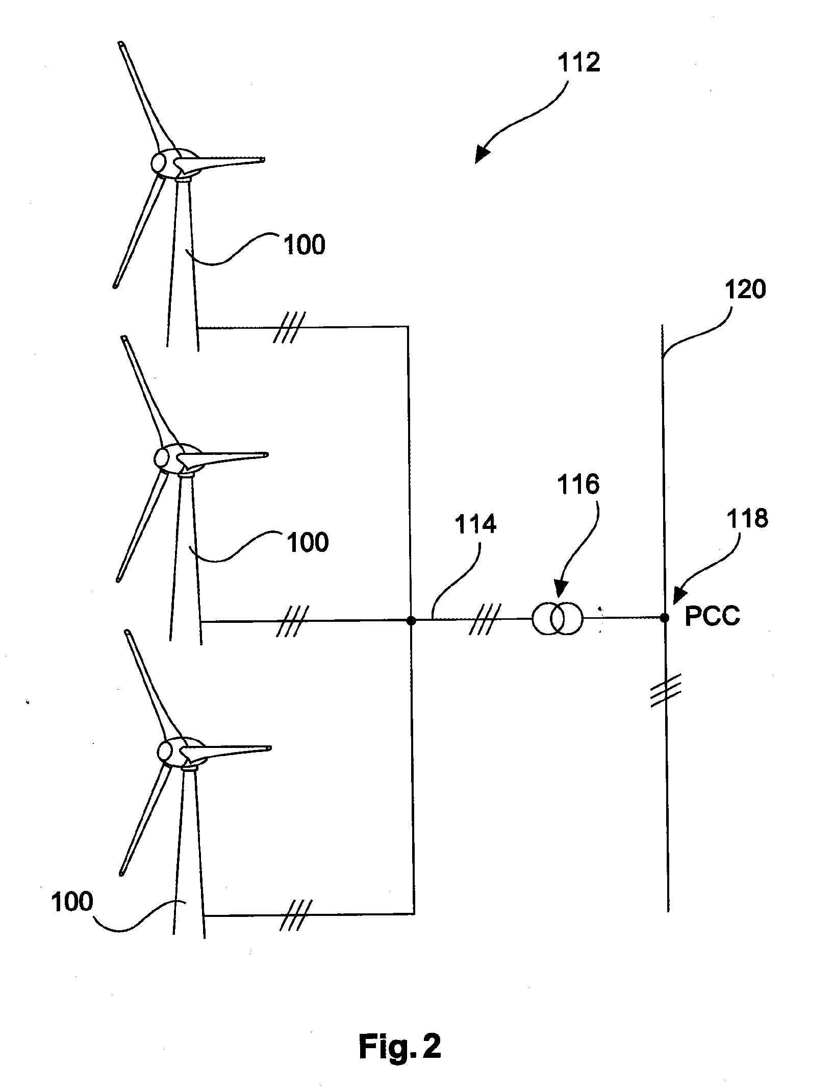
[0035]FIG. 2 shows a wind farm 112 with, for example, three wind turbines 100, which may be the same or different. The three wind turbines 100 are thus representative of a basically random number of wind turbines of a wind farm 112. The wind turbines 100 provide their power, in particular the generated electricity, via an electrical wind farm grid 114. The currents or powers, respectively, generated by the individual wind turbines 100 are added up. Most often, a transformer 116 will be provided, which transports the voltage at the wind farm to then feed it into the supply grid 120 at the feeding point 118, which is also generally referred to as a PCC. FIG. 2 is merely a simplified illustration of a...


PUM


Abstract

A method for feeding electrical energy into an electrical supply grid by means of a wind turbine or wind farm, where the wind turbine or wind farm converts kinetic energy from wind with variable speed to electrical energy, a wind speed is predicted based on a wind forecast and a reactive power to be fed in is calculated as predicted reactive power based on the predicted wind speed.

Description

BACKGROUND[0001]1. Technical Field[0002]The present invention relates to a method for feeding electrical energy into an electrical supply grid by means of a wind turbine or wind farm. The present invention, moreover, relates to a wind turbine for feeding electrical energy into an electrical supply grid, and the present invention relates to a wind farm for feeding electrical energy into an electrical supply grid.[0003]2. Description of the Related Art[0004]Feeding electrical energy into an electrical supply grid by means of wind turbines or by means of a wind farm comprising several wind turbines is a matter of common knowledge. It is also known that the wind turbine or wind farm is not only responsible for feeding energy, but also for grid support. So, what is assumed here as an AC grid is a common electrical supply grid.[0005]An early document that describes grid support by means of wind turbines is, for example, U.S. Pat. No. 6,965,174. This document describes, inter alia, the adj...

Claims


Application Information

Patent Timeline
Patent Type & Authority Applications(United States)
IPC IPC(8): H02P9/14F03D9/00
CPCH02P9/14F03D9/003F03D9/255H02J2300/28H02J3/381Y02A30/00H02J3/46Y02E10/72Y02E10/76
Inventor BEEKMANN, ALFRED
Owner WOBBEN PROPERTIES GMBH
Why Eureka
Try Eureka