Shielded RF Transmission Lines in Low Temperature Co-fired Ceramic Constructs and Method of Making Same

a co-fired ceramic and transmission line technology, which is applied in the direction of printed circuit manufacturing, printed circuit aspects, electrical equipment, etc., can solve the problem of limit in the miniaturization of printed circuitry, and achieve the effect of reducing or minimizing electric and/or magnetic field leakag

Inactive Publication Date: 2016-06-16
UNIVERSITY OF WINDSOR
View PDF4 Cites 2 Cited by
  • Summary
  • Abstract
  • Description
  • Claims
  • Application Information

AI Technical Summary

Benefits of technology

[0004]The present invention seeks to provide an integrated circuit construct or assembly which allows for the stacked assembly of printed ceramic substrate or tape layers. More particularly, the assembly incorporates a shielding enclosure extending about at least part of the electrical conductor traces and/or interconnects which fo

Problems solved by technology

While the use of LTCC tapes shows promise to the simplified customization and manufacture of multilayer circuit constructs, heretofore electric and/o

Method used


Image

  • Shielded RF Transmission Lines in Low Temperature Co-fired Ceramic Constructs and Method of Making Same
  • Shielded RF Transmission Lines in Low Temperature Co-fired Ceramic Constructs and Method of Making Same
  • Shielded RF Transmission Lines in Low Temperature Co-fired Ceramic Constructs and Method of Making Same

Examples


Embodiment Construction

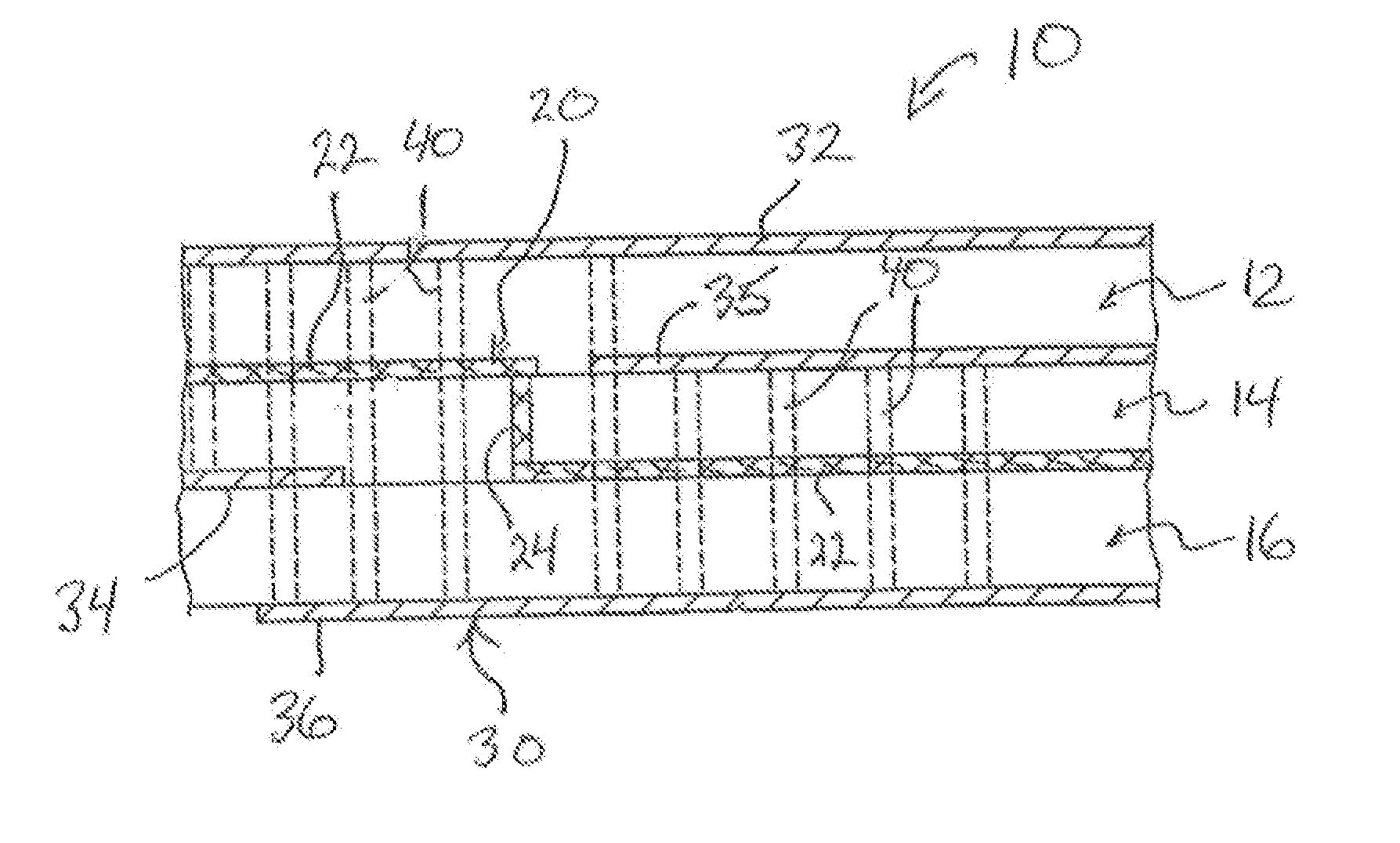
[0049]Reference may be had to FIG. 1 which illustrates an integrated circuit construct in the form of a shielded LTCC RF conductor assembly 10 in accordance with a preferred embodiment of the invention. For simplicity the RF conductor assembly 10 is shown formed as a three-layer construct. The conductor assembly 10 includes three stacked LTCC tape layers 12,14,16, and is provided internally with an electrical conductor framework 20 which provides the desired assembly circuitry, and a grounded shielding enclosure or cage 30. As will be described, the shielding cage 30 is provided in an orientation and with a spacing about the conductor framework 20 to minimize and / or reduce electrical and / or magnetic interference therewith. It is to be appreciated that while the assembly 10 is shown with three LTCC layers 12,14,16, the assembly 10 could be formed having fewer or greater number or tape layers, depending upon the final desired circuitry to be achieved.

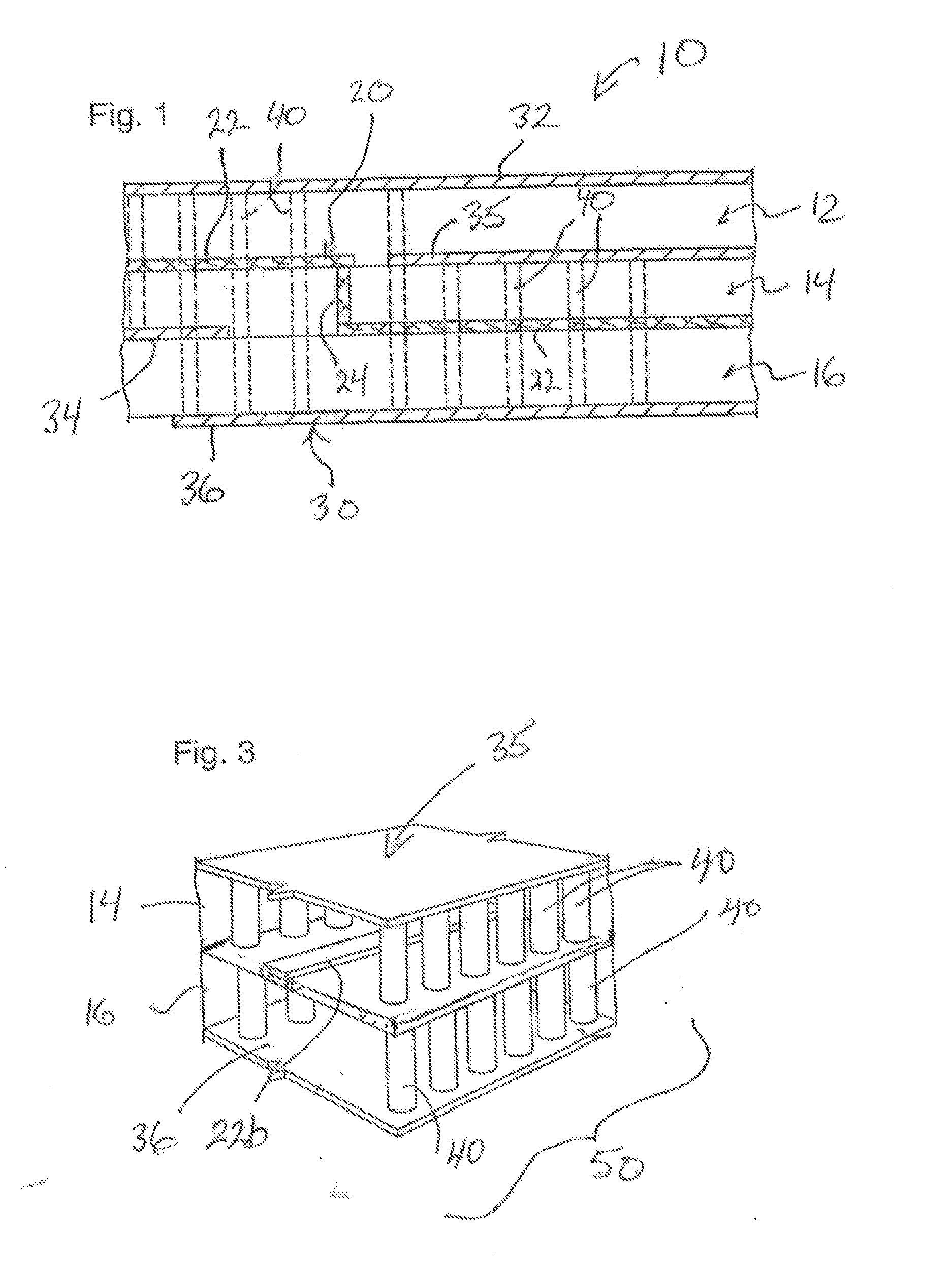
[0050]FIG. 2 shows in isolation th...


PUM


Abstract

An integrated circuit assembly which includes stacked printed ceramic substrate layers, and incorporates a shielding enclosure extending about the electrical conductor traces and interconnects which form the assembly circuitry. The shielding enclosure is configured to reduce electric and/or magnetic field leakage or interference with the traces and interconnects. The enclosure is provided as a cage about the assembly circuitry, and which is formed as arrays of ground conductors in electrical communication with ground plates.

Description

RELATED APPLICATIONS[0001]This application claims priority and the benefit of 35 USC §119(e) to U.S. Provisional Patent Application Ser. No. 62 / 091,713, filed 15 Dec. 2014, the disclosure of which is incorporated herein by reference in its entirety.BACKGROUND OF THE INVENTION[0002]Low temperature co-fired ceramic (LTCC) sheets or substrates and tapes such as GreenTape™ sold by DuPont, have proven useful in the manufacture of multilayer integrated circuits, circuit laminates, chip packages, RF modules, wiring boards and other such electronic constructs (hereinafter generally referred to as an integrated circuit “construct or assembly”). Typically LTCC substrates are farmed from glass (CaO—Al2O3—SiO2—B2O3) and alumina (Al2O3) compositions. The LTCC tapes function as a dielectric substrate onto or through which gold, silver or other suitable conductor strips may be printed using film screen printing methods in conjunction with metal deposition and etching technologies, to form internal...

Claims


Application Information

Patent Timeline
IPC IPC(8): H05K9/00H05K3/46H05K3/00H05K1/03H05K1/11
CPCH05K9/00H05K1/0306H05K3/4605H05K3/0088H05K1/115H01L21/4857H01L23/15H01L23/552H01L23/66H01L2924/0002H05K1/0218H05K2201/09609H01L2924/00
Inventor CHOWDHURY, SAZZADUR
Owner UNIVERSITY OF WINDSOR
Why Eureka
Try Eureka