In-bottle wine aerator
- Summary
- Abstract
- Description
- Claims
- Application Information
AI Technical Summary
Benefits of technology
Problems solved by technology
Method used
Image
Examples
second embodiment
[0038]an in-bottle aerator is illustrated in FIG. 6. In this embodiment, turbulent flow is induced by the shape of the aerator to induce the mixture of air with the fluid. The aerator 200 includes a body 202 having a cork-screw shape. The body 202 may be of varying diameters such that the body 202 can fit tightly within bottlenecks of varying diameters. The cork-screw shape of the body 202 directs fluid in a swirling motion along the curved surface 203 of the body 202. As the fluid travels from one end of the body to the other, the fluid is swirled around the body 202, resulting in turbulent flow. Turbulence or turbulent flow is characterized by rapid variation of pressure and velocity. The readily available supply of energy in turbulent flows tends to accelerate mixing or diffusivity of the fluid. Turbulent flow further creates eddies or swirls in which air can mix with or aerate the fluid. The aerator 200 is universal and can be inserted for flow in either direction.
Tapered Turbul...
third embodiment
[0039]an in-bottle aerator is illustrated in FIG. 7. The aerator 300 includes a cylindrical body 302. The cylindrical body 302 defines a pouring channel 308 that runs through the cylindrical body 302 from a proximal end 303 to a distal end 305. As discussed above with respect to the other embodiments, the body 302 may be of varying diameters such that the body 302 can fit tightly within bottlenecks of varying diameters. As fluid passes from the proximal end 303 to the distal end 305 of the pouring channel 308, the fluid passes over a plurality of ledges 310 created by the varying cross-section of the pouring channel 308 consisting of a plurality of converging sections 312. The fluid is initially accelerated as it passes through each converging section 312, lowering the pressure of the fluid. When the fluid passes over the ledges 310, the fluid is allowed to expand and decrease in velocity, increasing the pressure of the fluid and creating eddies or swirls in the flow. These eddies o...
fourth embodiment
[0040]an in-bottle aerator is illustrated in FIG. 8. The aerator 400 includes a tapered cylindrical body 402 with a plurality of wedges 404 oriented approximately every 90 degrees around the circumference of the body. Each of the wedges 404 extends along a length of the cylindrical body 402. Fluid passing over the wedges 404 is induced to mix with air. Wine flows from the tapered cylindrical body 402 to the plurality of wedges 404. This design aerates the liquid by increasing the surface area of wine in contact with oxygen.
Finite Element and Compressive Stress Analysis of the Venturi Design
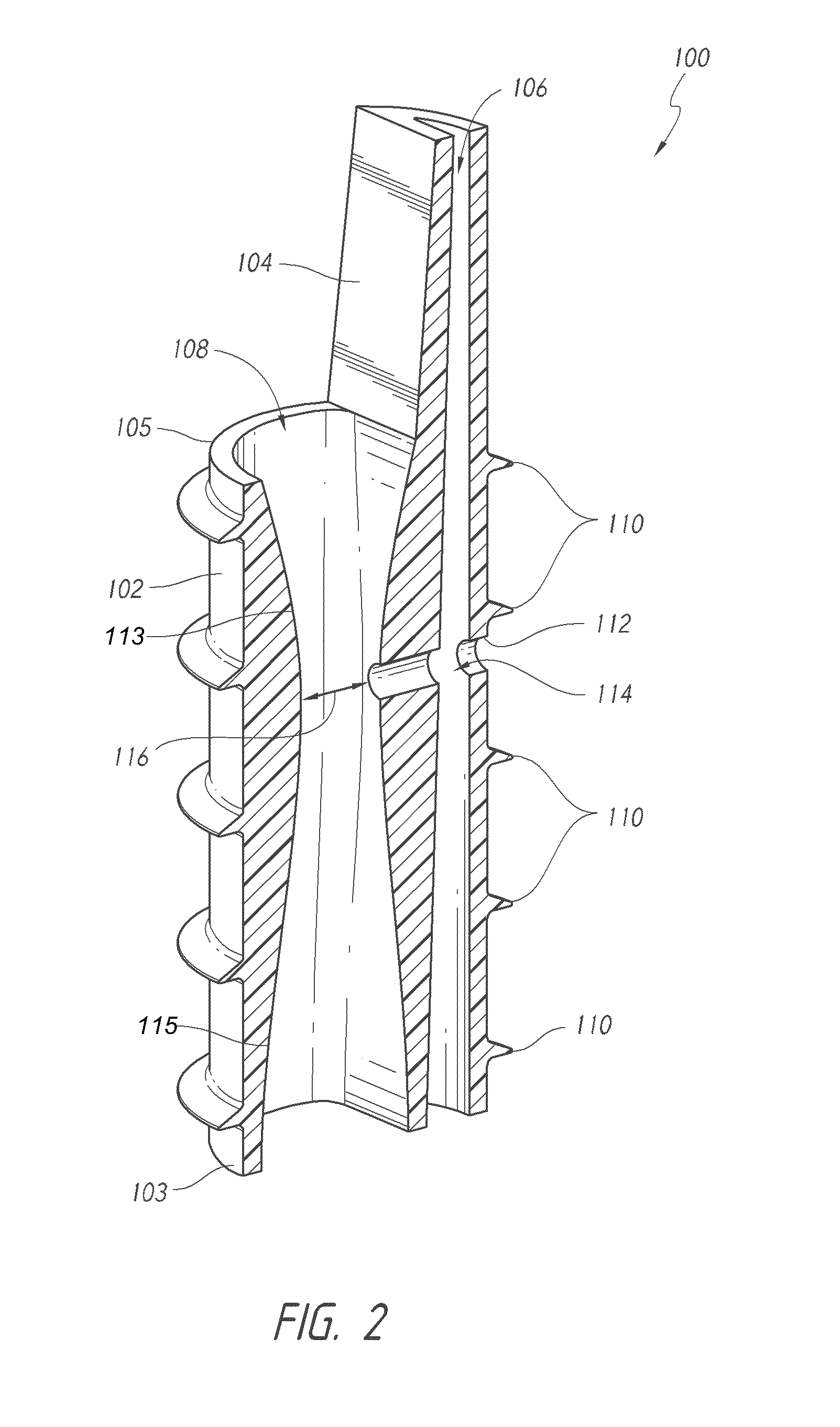
[0041]A compressive stress analysis was performed on the Venturi design. The analysis utilized the basic cylinder press fit principle: interference between an outer hollow cylinder and an inner full cylinder results in radial and hoop stresses on the inner cylinder. The aerator was press fit into the bottle neck, essentially deforming the silicon rubber seal and causing the surface to feel radial ...
PUM
| Property | Measurement | Unit |
|---|---|---|
| Flow rate | aaaaa | aaaaa |
| Diameter | aaaaa | aaaaa |
| Diameter | aaaaa | aaaaa |
Abstract
Description
Claims
Application Information
 - R&D
- Intellectual Property
- Life Sciences
- Materials
- Tech Scout
- Unparalleled Data Quality
- Higher Quality Content
- 60% Fewer Hallucinations
Browse by: Latest US Patents, China's latest patents, Technical Efficacy Thesaurus, Application Domain, Technology Topic, Popular Technical Reports.
© 2025 PatSnap. All rights reserved.Legal|Privacy policy|Modern Slavery Act Transparency Statement|Sitemap|About US| Contact US: help@patsnap.com


