Additive manufacturing method and apparatus

a manufacturing method and additive technology, applied in the field of additive manufacturing processes, can solve the problems of insufficient support for objects, difficult to remove the supports in repeatable fashion, and difficult to remove the supports b>, and achieve the effect of facilitating the removal of the supports and facilitating the breakag

Inactive Publication Date: 2016-06-23
RENISHAW PLC
View PDF3 Cites 25 Cited by
  • Summary
  • Abstract
  • Description
  • Claims
  • Application Information

AI Technical Summary

Benefits of technology

[0011]The invention facilitates removal of the supports from the object through the lever action whilst ensuring that the supports are separated at repeatable positions defined by the frangible structures.
[0012]The frangible structures have a different structure to the main body such that, under the input force, the frangible structures break more readily than the main body. The main body may have sufficient structural integrity such that an input force can be applied to cause the main body to pivot to break the frangible structures without significant deformation of the main body, e.g. the structure of the main body when released from the object is substantially the same as during the build. The force required to significantly deform the main body may be much greater than the input force required to break the frangible structures.

Problems solved by technology

However, it has been found that it is difficult to remove these supports in a repeatable fashion such that each object (for example in a series of nominally identical objects) looks the same.
It is very difficult to remove the supports 1a located in the recess 3.
However, weakening of the regions of the supports can result in insufficient support for the object.
For example, thermally generated forces urging the object to curl during the build can cause the object to break away from the supports at these weakened break points causing distortion and possible failure of the build.

Method used


Image

  • Additive manufacturing method and apparatus
  • Additive manufacturing method and apparatus
  • Additive manufacturing method and apparatus

Examples


Embodiment Construction

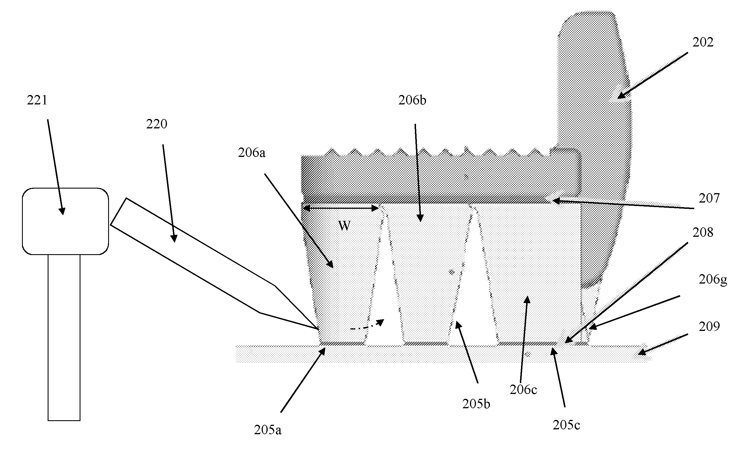
[0048]Referring to FIGS. 2a to 2c, a support structure 101 for supporting an object 2 during additive manufacturing, such as SLM or SLS, comprises a plurality of separate supports 105a to 105h for supporting the object. Each support comprises a main body 106a to 106h attached to the object by a 2-dimensional pattern of frangible structures 107 that can be broken by application of a force to the main body 106a to 106h. The main body 106a to 106h is a block of material solidified using the SLM or SLS process. In FIG. 2c a regular grid pattern of frangible elements 107 is shown for the supports 105c, 105d, 105a and 105f. Each support further comprises further frangible structures 108 that attach the main body 106a to 106h to the build platform (not shown).

[0049]The main bodies 106a to 106h are arranged to define gaps 112 therebetween into which the main bodies 106a to 106h can be displaced by an input force. Each gap 112 is dimensioned such that each main body 106a to 106h has sufficie...


PUM

PropertyMeasurementUnit
heightaaaaaaaaaa
distancesaaaaaaaaaa
distancesaaaaaaaaaa

Abstract

An additive manufacturing method including building an object layer-by-layer by, repeatedly, providing a layer of material on build platform and scanning a beam across the layer to consolidate material. A plurality of supports may be provided for supporting object during build. Each support may include main body attached to the object by 2-dimensional pattern of frangible structures. The method may further include applying input force to main body to displace main body to break the frangible structures. Also relates to a support structure that may be used in this method. The support structure may include plurality of supports for supporting the object, each support including main body attached to object by a 2-dimensional pattern of frangible structures. The supports may be arranged such that main bodies define a gap therebetween into which at least one of main bodies can be displaced by an input force to break the frangible structures.

Description

SUMMARY OF INVENTION[0001]This invention concerns an additive manufacturing method and apparatus and, in particular, but not exclusively, a method and apparatus of building a support for an object built using additive manufacturing such that the object can be easily released from the support at the end of the build. The invention has particular application to the building of an object and associated support structure from metal powder.BACKGROUND[0002]In additive manufacturing processes, such as selective laser melting (SLM) or selective laser sintering (SLS), objects are built layer-by-layer by consolidation of a material, such as powder material, using a focussed high energy beam, such as a laser beam or electron beam. In SLM or SLS, successive layers of powder are deposited on to a build platform and a focussed laser beam scanned across portions of each layer corresponding to a cross-section of the object being constructed such that the powder at the points the laser scans are con...

Claims


Application Information

Patent Timeline
Patent Type & Authority Applications(United States)
IPC IPC(8): B22F3/105B23K26/342B23K37/04B22F3/24
CPCB22F3/1055B22F3/24B23K26/342B33Y40/00B22F2003/1058B22F2003/247B33Y10/00B23K37/04B29C64/153B29C64/40Y02P10/25B22F10/28B22F10/43B22F10/80B22F10/47B22F10/66
Inventor DIMTER, MARCMAYER, RALPH
Owner RENISHAW PLC
Why Eureka
Try Eureka