Aircraft landing gear

Active Publication Date: 2016-06-23
SAFRAN LANDING SYSTEMS
View PDF20 Cites 2 Cited by
  • Summary
  • Abstract
  • Description
  • Claims
  • Application Information

AI Technical Summary

Benefits of technology

[0009]The obstacles constitute a toothed ring with which the lead screw of the driving actuator cooperates, said toothed ring being simple to manufacture and relatively light in weight since it consists only of the obstacles and the means for fixing them to the rim. Moreover, the use of the lead screw makes it possible to obtain a mechanical connection having a high demultiplication ratio. It is therefore possible to reduce the torque that an electric motor of the driving actuator must develop at the same time as increasing the speed of said motor, which makes it possible to reduce the overall size and the mass of said motor of the actuator.
[0010]The use of obstacles projecting from the lateral face of the rim, when these obstacles are placed at a certain distance from the centre of the rim, makes it possible to position the driving actuator away from a highly congested area situated between the landing gear leg and the wheel. Sufficient space is therefore available for

Problems solved by technology

Now, the rotation speeds at which the wheels of the aircraft must be driven and the torques

Method used


Image

  • Aircraft landing gear
  • Aircraft landing gear
  • Aircraft landing gear

Examples


first embodiment

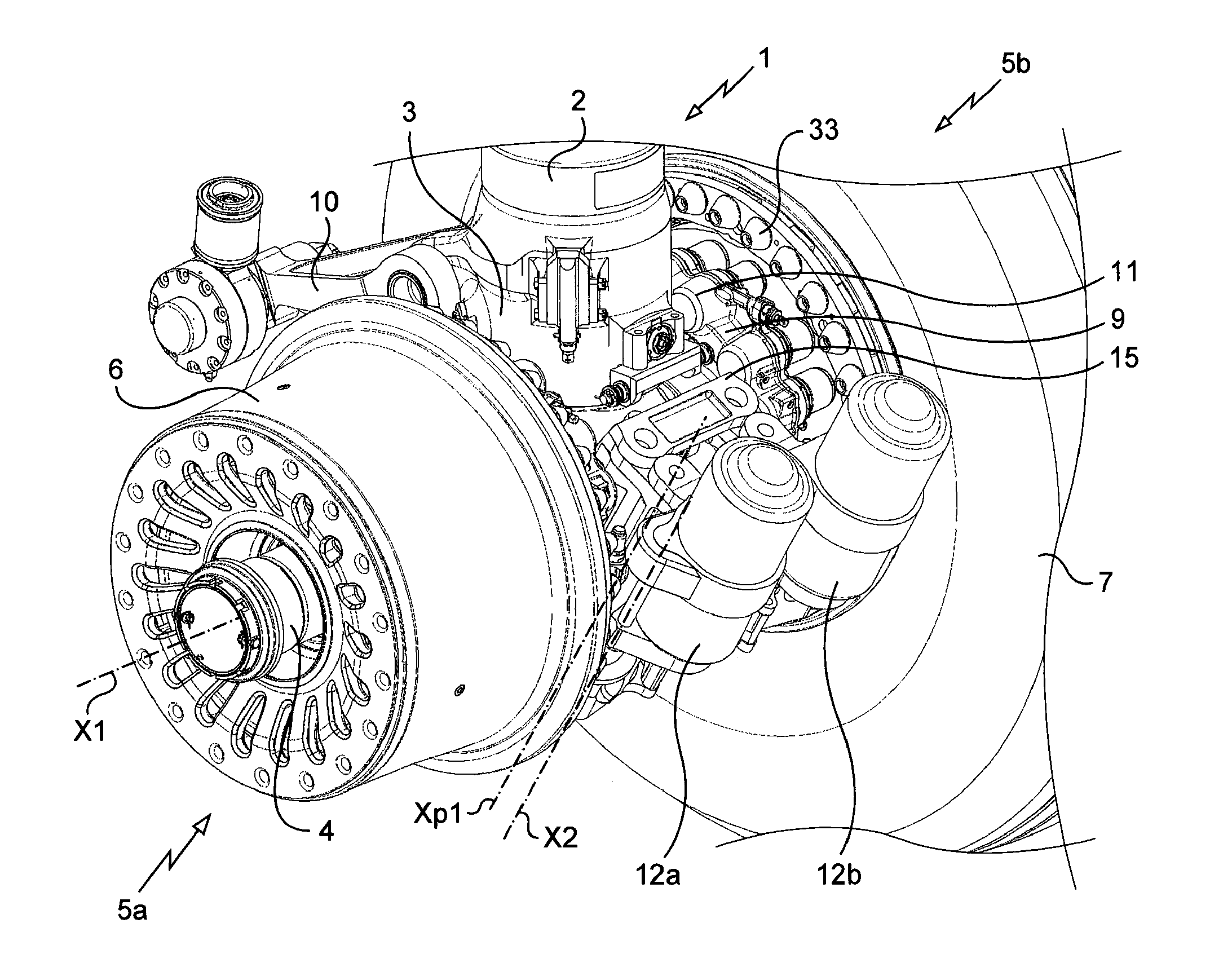
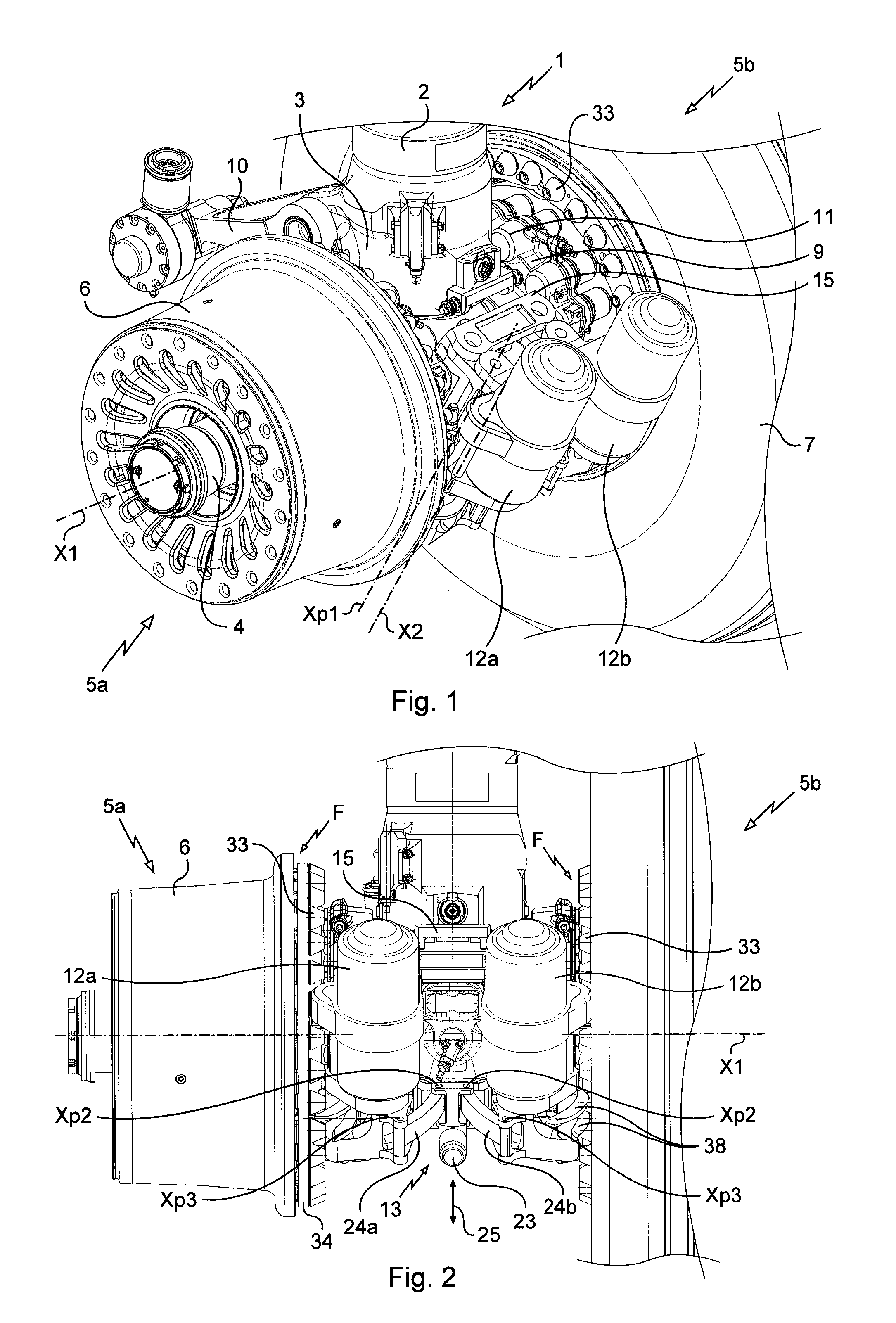
[0024]Referring to FIGS. 1 and 2, the landing gear 1 in accordance with the invention here includes in the conventional way a strut assembly 2 articulated to the structure of an aircraft in which a sliding rod 3 is mounted to slide telescopically. The sliding rod 3, represented here in an entirely retracted position, carries at its end an axle 4 supporting a first wheel 5a and a second wheel 5b. A compass arm 10 connects the strut assembly 2 and the sliding rod 3 to ensure sliding without rotation of the sliding rod 3.

[0025]Each wheel 5 includes a rim 6 that carries a tyre 7 and that is mounted to turn on the axle 4 about an axis of the axle 4 or first rotation axis X1 by means of bearings. Each wheel 5 is furthermore equipped with a brake adapted to brake the wheel 5, the brake including a stack of carbon disks inside the rim 6 of the wheel 5 and not visible in the figures, a ring 9 fixed to the axle 4, and a plurality of electromechanical actuators 11 carried by the ring 9 and ada...

second embodiment

[0040]In the invention, and referring to FIG. 8, the rollers 39 are mounted to pivot freely about axes X3 parallel to the first rotation axis X1. Each roller 39 includes here a base 41 forming a fixed interior race of a ball bearing, an upper part 42 forming an exterior race of the ball bearing, and balls 43 disposed on a raceway of the exterior race. The upper part 42 of each roller 39 includes a first threaded hole 44. The base 41 includes a second threaded hole 45 passing through the base 41 from one side to the other and extending the first threaded hole 44. When the roller 39 is mounted on the support ring 34, the first and second threaded holes 44, 45 are extended by a third threaded hole 46 in the support ring 34. The roller 39 is fixed to the support ring 34 by a bolt extending through the first and second threaded holes 44, 45 and into the third threaded hole 46.

[0041]The invention is not limited to the particular embodiments that have just been described and to the contrar...


PUM


Abstract

An aircraft landing gear including an axle and a wheel (5) that includes a rim (6) mounted to turn on the axle about a first rotation axis (X1), the landing gear further comprising an actuator (12) for driving the wheel (5) in rotation. The rim (6) includes obstacles (33) that project from a lateral face (F) of the rim and the driving actuator includes a lead screw (32) mounted to turn about a second rotation axis (X2) perpendicular to the first rotation axis (X1) and adapted to cooperate with the obstacles of the rim to drive the wheel in rotation.

Description

[0001]The invention concerns an aircraft landing gear on which is mounted an actuator for driving a wheel in rotation, said actuator including a lead screw cooperating with obstacles projecting from a lateral face of the rim of the wheel.BACKGROUND OF THE INVENTION[0002]A certain number of reasons are pushing aircraft manufacturers to attempt to motorize the wheels of the aircraft, notably using driving actuators equipped with electric motors. Such motorization in fact has major environmental and economic advantages (reduction of fuel consumption, reduction of noise when taxiing, etc.), and makes it possible to implement new functions: manoeuvring of the aircraft when the engines are stopped, reversing, remote control of the aircraft on the ground, etc.[0003]Those designing and fitting aircraft wheel driving actuators must make the actuators conform to numerous technical requirements specified by aircraft manufacturers that are particularly constraining.[0004]The increase in the mas...

Claims


Application Information

Patent Timeline
IPC IPC(8): B64C25/40B64C25/34
CPCB64C25/34B64C25/405Y02T50/80
Inventor MAZARGUIL, NICOLAS
Owner SAFRAN LANDING SYSTEMS
Why Eureka
Try Eureka