Cable system

a cable system and cable technology, applied in the field of cable systems, can solve the problems of inability to transmit signals, large burden, cable slackening, etc., and achieve the effect of simple information processing, reliable and swift removal

Active Publication Date: 2016-06-23
TOPY INDUSTRIES
View PDF0 Cites 9 Cited by
  • Summary
  • Abstract
  • Description
  • Claims
  • Application Information

AI Technical Summary

Benefits of technology

[0034]According to the cable system of present invention, a slack in the cable may be reliably and swiftly removed by simple information processing.

Problems solved by technology

This is because, if the reel is installed in a base station, the travelling body has to draw out the cable from the reel in the base station, and the burden is great.
However, in the case where the reel is mounted on the travelling body as described above, there is a problem that, because a thin long cable is wound around the reel, the cable may be slackened and be caught at a part of the travelling body or the cable may get tangled, becoming unable to transmit signals, and as a result, the travelling body may become immobilized.
However, the basic control as described above alone may cause an inconvenience.
Moreover, the basic control as described above alone may also cause inconveniences as follows.
As a result, the cable is slackened, and this slackened portion may get entangled with the reel rotating in the unreeling direction, or may be spread near the reel in a disorderly manner, or may get caught at a part of the travelling body, thereby immobilizing the travelling body and preventing it from returning.

Method used


Image

  • Cable system
  • Cable system
  • Cable system

Examples


Embodiment Construction

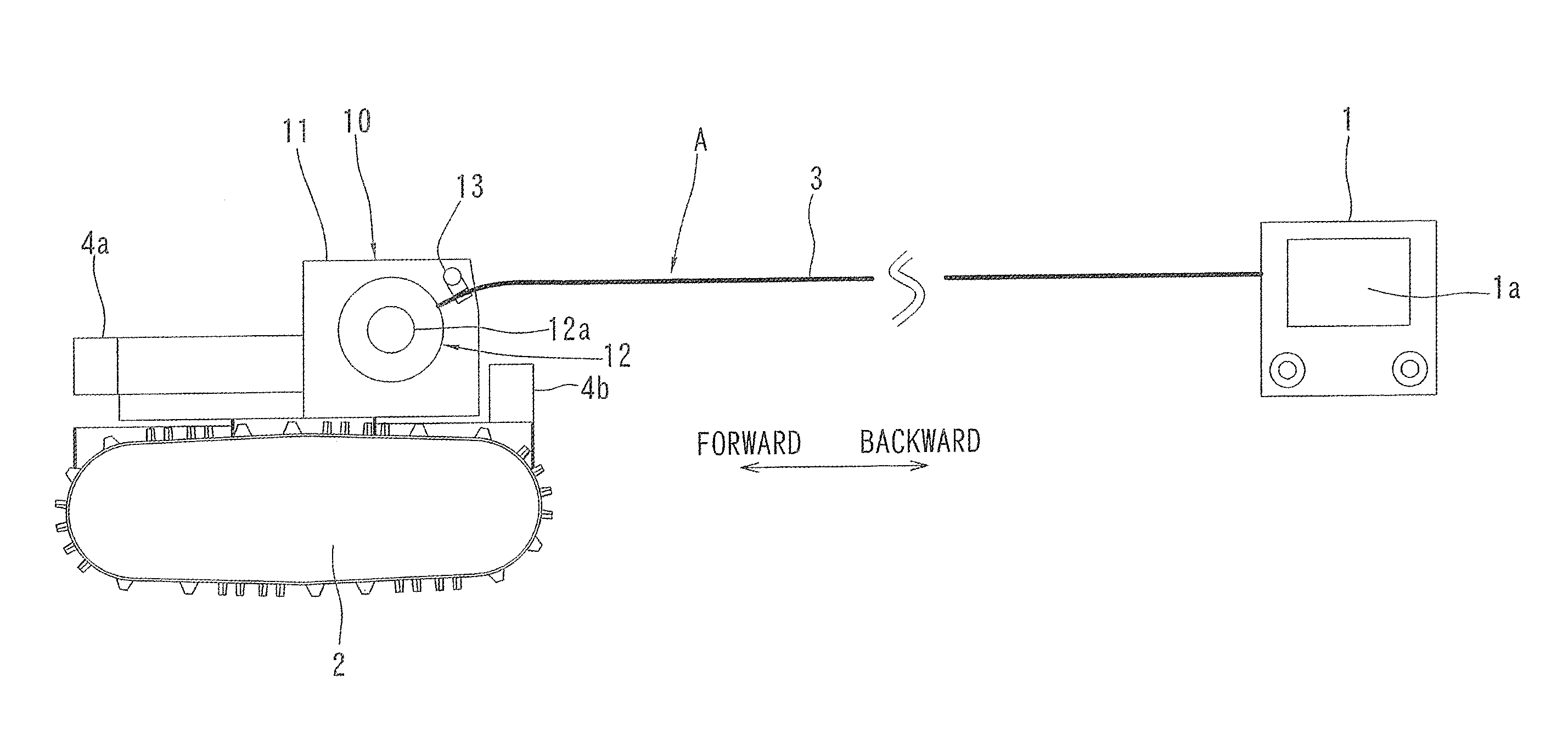
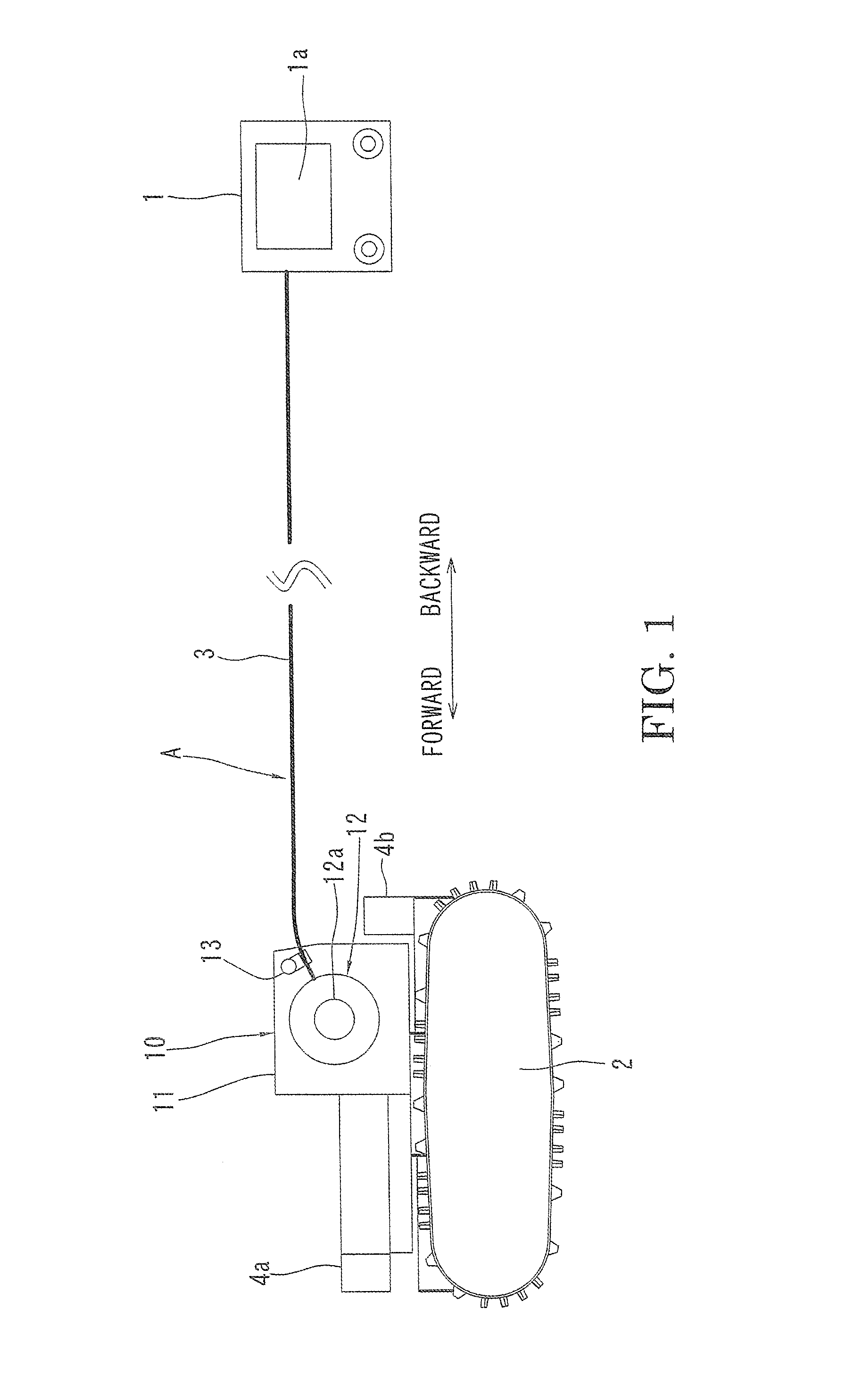
[0041]Hereinafter, an exploration system including a cable system A according to an embodiment of the present invention will be described with reference to the drawings. As shown in FIG. 1, the exploration system includes a remote controller 1 (base device), a crawler-type travelling body 2, and a long cable 3 for connecting the remote controller 1 and the travelling body 2.

[0042]The remote controller 1 includes a monitor display 1a. The travelling body 2 includes a battery (not shown) and a motor for travelling. The cable 3 has optical fibers embedded therein, and transmits signals.

[0043]Video cameras 4a and 4b (exploration devices) are mounted on the travelling body 2. The video camera 4a takes images of the view ahead of the travelling body 2, and the video 4b captures the view behind the travelling body 2. As the exploration device, a sensor such as an infrared sensor, a chemical detection sensor, a temperature sensor, or a radiation sensor may be used together with or instead o...


PUM


Abstract

A cable system A includes a cable 3 for connecting a base device 1 and a travelling body 2, a reel device 10 mounted on the travelling body 2, a motor controller 40 for controlling a motor 15 of the reel device 10, and a rotary encoder 16 (rotation sensor) for detecting rotation of a reel 12. The motor controller 40 basically makes the motor 15 free, when the reel 12 is rotating in an unreeling direction, and basically applies a rotational torque in a reeling direction to the reel 12, when the reel 12 is rotating in the reeling direction. Furthermore, even if the reel 12 is rotating in the unreeling direction, if an unreeling speed of the cable 3 exceeds a travelling speed of the travelling body 2, the rotational torque in the reeling direction is applied to the reel 12. Slackening of the cable 3 is thereby prevented.

Description

TECHNICAL FIELD[0001]The present invention relates to a cable system equipped with a reel device.BACKGROUND ART[0002]It is well known to remotely control a travelling body to travel by a remote controller (base device). A video camera is mounted on the travelling body, and image signals from the video camera are transmitted to the remote controller, and an operator operates the remote controller while looking at a monitor display accompanying the remote controller. Remote control signals from the remote controller are transmitted to the travelling body to cause the travelling body to move forward or backward, or to turn.[0003]Systems for transmitting the image signals and the remote control signals include a wireless system and a wired system. A wired system is mainly adopted when the travelling body is used in a place where radio waves are not easily received, such as in a building with winding passages or under water.[0004]In rescue operation or exploration, the work site may be w...

Claims


Application Information

Patent Timeline
Patent Type & Authority Applications(United States)
IPC IPC(8): B65H75/42H02G11/02B65H75/44
CPCB65H75/42H02G11/02B65H75/4484H02G11/00B65H75/425B65H75/4486B65H2701/32
Inventor TSUKUI, SHINGOOOMURA, SEIJIIWAKI, HIDEKAZU
Owner TOPY INDUSTRIES
Why Eureka
Try Eureka