Dual check backflow preventer

a preventer and backflow technology, applied in the direction of functional valve types, valve housings, service pipes, etc., can solve the problems of exhibiting substantial flow turbulence, unable to hold static differential pressure on the check disc, and possible leakage path past the check disc, etc., to achieve the effect of reducing flow turbulen

Active Publication Date: 2016-06-23
CONBRACO IND
View PDF4 Cites 22 Cited by
  • Summary
  • Abstract
  • Description
  • Claims
  • Application Information

AI Technical Summary

Benefits of technology

[0005]It is therefore an object of the present invention to provide a backflow preventer that reduces flow turbulence during normal operation.
[0006]It is another object of the invention to provide a backflow preventer that includes an improved diaphragm with enhanced stress against rupture.
[0007]It is another object of the invention to provide a backflow preventer that includes improved tolerances and sealing characteristics between and among components.
[0008]It is another object of the invention to provide a backflow preventer that includes a check plate adapted to reduce exposed areas of the diaphragm, improve flow capacity and head pressure loss.
[0011]In accordance with another embodiment of the invention, the downstream check disc assembly includes a downstream check disc integrally formed with a stem extending upstream thereof and mounted in an aperture in a central hub formed in a flow opening in a wall of the housing for movement between an normally open, flow position and a closed position preventing backflow of liquid through the outlet.
[0017]In accordance with another embodiment of the invention, the downstream check disc assembly includes a check disc integrally formed with a stem extending upstream thereof and mounted in an aperture in a central hub formed in a flow opening in a wall of the housing for movement between an normally open, flow position and a closed position preventing backflow of liquid through the outlet. The downstream check disc assembly includes a check disc integrally formed with a stem extending upstream thereof and mounted in an aperture in a central hub formed in a flow opening in a wall of the housing for movement between an normally open, flow position and a closed position preventing backflow of liquid through the outlet.

Problems solved by technology

In the normal, open operating condition the backflow preventer 1 exhibits substantial flow turbulence as a result of the configuration of the inlet cavity components that increase head loss and chatter at low flow conditions.
This assembly technique presents the possibility of stem wall cracks during assembly which can lead to a possible leak path past the check disc and failure of the check discs to hold static differential pressures.

Method used


Image

  • Dual check backflow preventer
  • Dual check backflow preventer
  • Dual check backflow preventer

Examples


Embodiment Construction

Prior Art

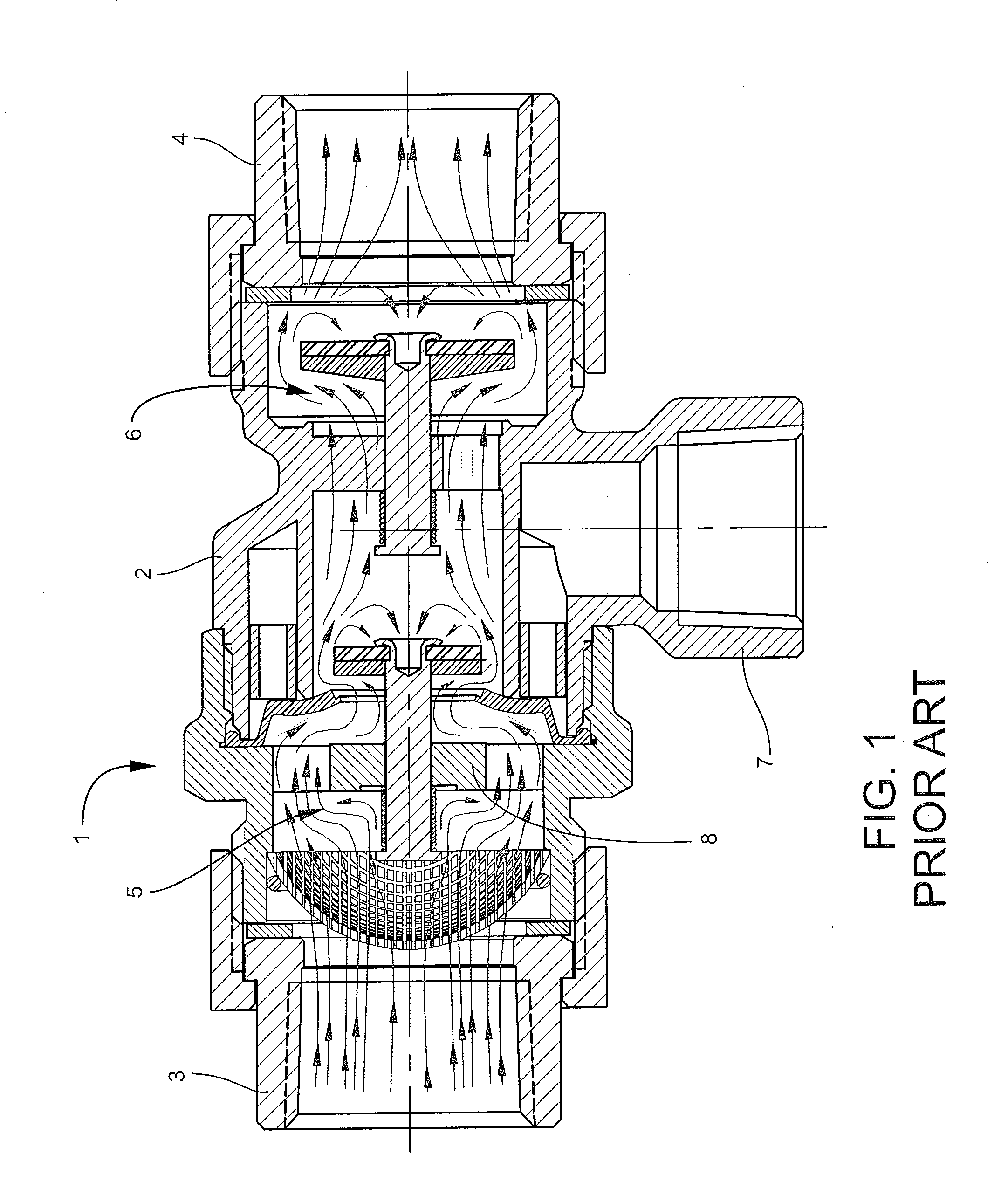
[0033]Referring now to FIG. 1, a prior art backflow preventer is shown at reference numeral 1. Broadly described, the backflow preventer 1 includes a housing 2 attached to an inlet 3 and outlet 4. An upstream check disc assembly 5 and downstream check disc assembly 6 each operate to prevent backflow. Any backflow liquid flowing upstream past the downstream check disc assembly 6 is diverted to a vent 7, and prevented from flowing past the upstream check disc assembly 5, which includes the threaded cap. A check plate 8, which is an integral part of the threaded cap and a part of the check disc assembly 5, is provided with a series of flow ports positioned around the periphery allows downstream water flow to and past the upstream check disc.

[0034]In the normal, open operating condition the backflow preventer 1 exhibits substantial flow turbulence as a result of the configuration of the inlet cavity components that increase head loss and chatter at low flow conditions. The prio...


PUM


Abstract

A backflow preventer that includes a housing having an inlet and an outlet adapted to be mounted in a liquid flow configuration in a liquid supply circuit. An upstream check disc assembly is positioned in the housing downstream of the inlet, and includes an upstream check plate supporting a downstream diaphragm. An upstream check disc is positioned downstream of the diaphragm and integrally formed with an upstream stem mounted in an aperture in a central hub formed in the check plate for movement between a normally open, flow position and a closed position preventing backflow of liquid through the inlet. A downstream check disc assembly is positioned in the housing downstream from the upstream check disc assembly. A vent discharges liquid to atmosphere upstream of the downstream check disc assembly.

Description

TECHNICAL FIELD AND BACKGROUND OF THE INVENTION[0001]This invention relates to a dual check backflow preventer designed to protect liquid supply lines from back-siphonage or back-pressure of non-potable liquids. Backflow preventers of this type have two independently acting and spring-loaded check valves constructed of a corrosion resistant material. Such devices also typically have an intermediate atmospheric vent to insure protection from backflow conditions. The backflow preventer of this application is described with reference to its use in a water supply circuit, which is a principal usage. However, it will be understood that the subject matter of this invention is not limited to use with water, but is applicable to any liquid circuit where backflow is not desirable or permitted.[0002]During normal flow operation, the vent valve is closed, and the two check valves, which are in a flow series configuration, are open, allowing water to flow through the unit in a single direction....

Claims


Application Information

Patent Timeline
Patent Type & Authority Applications(United States)
IPC IPC(8): F16K17/02F16K25/00E03B7/07F16K27/02
CPCF16K17/02E03B7/077F16K25/005F16K27/0209E03C1/106E03C1/108F16K15/063Y10T137/7838
Inventor CELLEMME, RAYMOND E.RODRIGUEZ, BERTITO TUBO
Owner CONBRACO IND
Why Eureka
Try Eureka