Pressure-Sensitive Touch Panel

Active Publication Date: 2016-06-23
CAMBRIDGE TOUCH TECH
View PDF4 Cites 81 Cited by
  • Summary
  • Abstract
  • Description
  • Claims
  • Application Information

AI Technical Summary

Benefits of technology

[0052]Thus, the layer structure for a touch panel can be fabricated without the need for complex and/or expensive deposition of patterned electrode on the layer of piezoelectric materia

Problems solved by technology

Although projected capacitance touch panels can usually differentiate between single-touch events and multi-touch events, they suffer the drawback of not being able to sense pressure.
Thus, projected capacitance touch panels tend to be unable to distinguish between a relatively tight tap and a relatively heavy press.
However, the need for a measureable displacement can make it more difficult to use a glass touch surface and can cause problems with material f

Method used


Image

  • Pressure-Sensitive Touch Panel
  • Pressure-Sensitive Touch Panel
  • Pressure-Sensitive Touch Panel

Examples


Example

[0121]In the following description, like parts are denoted by like reference numerals.

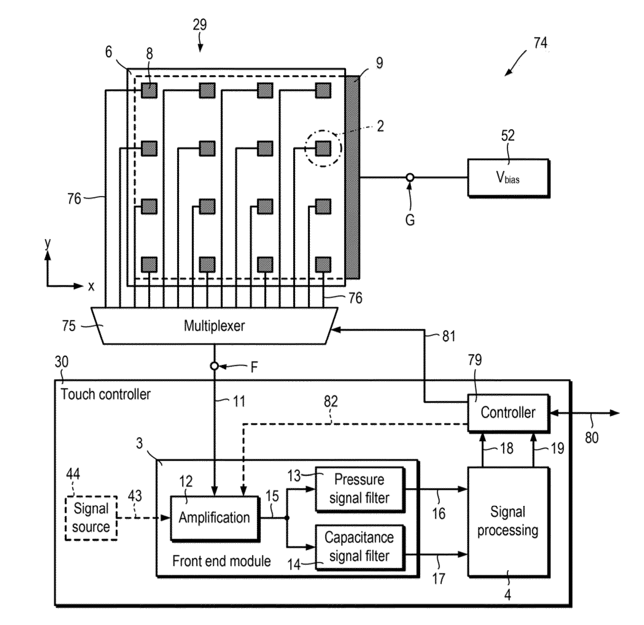
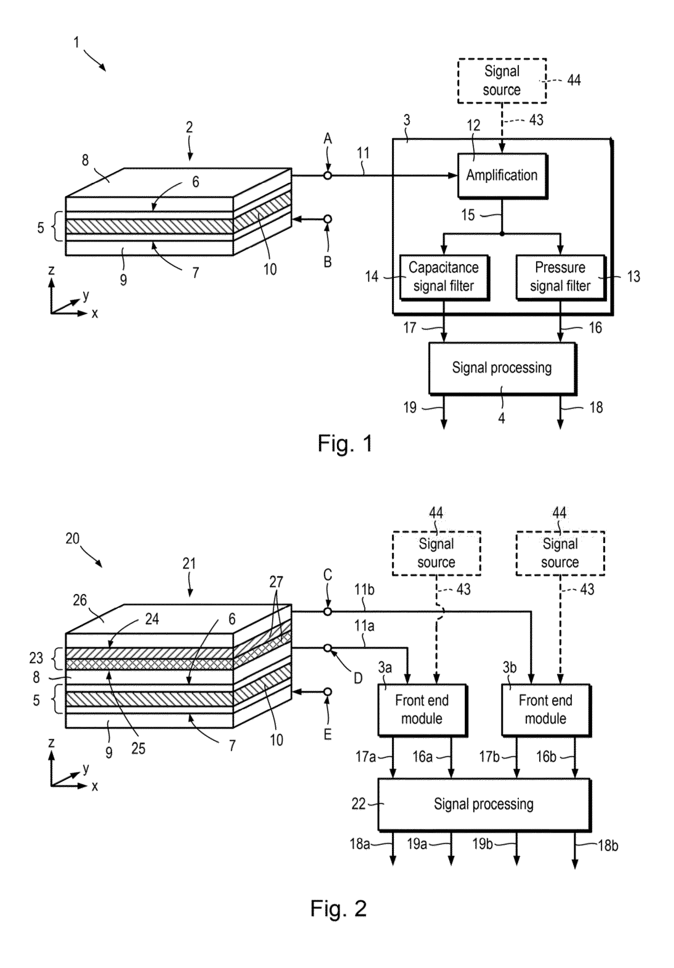
[0122]First combined capacitance and pressure sensing apparatus and first touch sensor: FIG. 1 schematically illustrates a first apparatus 1 for combined capacitive and pressure sensing which includes a first touch sensor 2, a front end module 3, and a first signal processing module 4.

[0123]The first touch sensor 2 includes a layer structure 5 having a first face 6 and a second, opposite, face 7, a first electrode 8 and a second electrode 9. The layer structure 5 includes one or more layers, including at least a layer of piezoelectric material 10. Each layer included in the layer structure 5 is generally planar and extends in first x and second y directions which are perpendicular to a thickness direction z. The one or more layers of the layer structure 5 are arranged between the first and second faces 6, 7 such that the thickness direction z of each layer of the layer structure 5 is perpendicular ...


PUM


Abstract

An apparatus for combined capacitance and pressure sensing is described. The apparatus includes a multiplexer (75) having a plurality of inputs (76) and an output (F), a touch panel (29), and a front end module (3). The touch panel includes a layer structure (5; FIG. 15) comprising one or more layers, each extending perpendicularly to a thickness direction, the one or more layers including a layer of piezoelectric material (10; FIG. 15), the layer structure having first (6) and second (7; FIG. 15) opposite faces, and the layer(s) arranged between the first and second faces such that the thickness direction of each layer is perpendicular to the first and second faces. The touch panel also includes a plurality of first electrodes (8) disposed on the first face, each first electrode connected to a respective input of the multiplexer. The touch panel also includes at least one second electrode (9) disposed on the second face. The front end module is configured to receive an input signal (11) from the multiplexer output. The front end module includes a first stage (12) configured to provide an amplified signal based on the input signal, and a second stage comprising first (13) and second (14) frequency-dependent filters configured to receive the amplified signal and to provide respective first (16) and second (17) filtered signals. The first filtered signal has a first frequency bandwidth, and the second filtered signal has a second frequency bandwidth which has a relatively higher start-frequency than the first frequency bandwidth.

Description

CROSS REFERENCES TO RELATED APPLICATIONS[0001]The present application claims priority to and the benefit of co-pending U.S. Provisional Patent Application No. 62 / 095,853 filed Dec. 23, 2014, the entire contents of which are hereby incorporated by reference.FIELD OF THE INVENTION[0002]The present invention relates to a touch panel for combined capacitive and pressure sensing.BACKGROUND[0003]Resistive and capacitive touch panels are used as input devices for computers and mobile devices. One type of capacitive touch panel, projected capacitance touch panels, is often used for mobile devices because an exterior layer may be made of glass, providing a hard surface which is resistant to scratching. An example of a projected capacitance touch panel is described in US 2010 / 0079384 A1.[0004]Projected capacitance touch panels operate by detecting changes in electric fields caused by the proximity of a conductive object. The location at which a projected capacitance touch panel is touched is ...

Claims


Application Information

Patent Timeline
IPC IPC(8): G06F3/041G06F3/044
CPCG06F3/0416G06F3/044G06F2203/04106G06F2203/04103G06F3/0414G06F2203/04105G06F3/04166G06F3/0443G06F3/0445G06F3/0446
Inventor NATHAN, AROKIALAI, JACKSON CHI-SUNCHA, SUK-BAECHURCH, CORBIN
Owner CAMBRIDGE TOUCH TECH
Why Eureka
Try Eureka