
Capacitive fingerprint sensor with sensing elements comprising timing circuitry

Active Publication Date: 2016-06-23
FINGERPRINT CARDS ANACATUM IP AB
View PDF5 Cites 16 Cited by
  • Summary
  • Abstract
  • Description
  • Claims
  • Application Information

AI Technical Summary

Benefits of technology

The patent aims to improve capacitive fingerprint sensing devices by using thick protective coatings to enhance sensing performance. The objective is to overcome the shortcomings of existing technologies.

Problems solved by technology

This, however, requires a relatively large capacitance between each of sensing structure and finger.
If the readout frequency is increased from, say, 1 MHz to, say, 20 MHz, the difference in conduction time to different sensing elements may make it difficult or even practically impossible to fulfill measurement-related timing requirements using external, central timing control.

Method used


Image

  • Capacitive fingerprint sensor with sensing elements comprising timing circuitry
  • Capacitive fingerprint sensor with sensing elements comprising timing circuitry
  • Capacitive fingerprint sensor with sensing elements comprising timing circuitry

Examples


Embodiment Construction

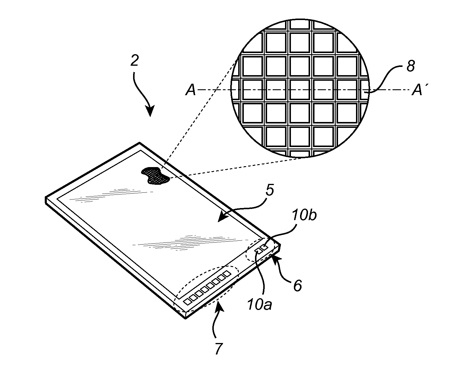
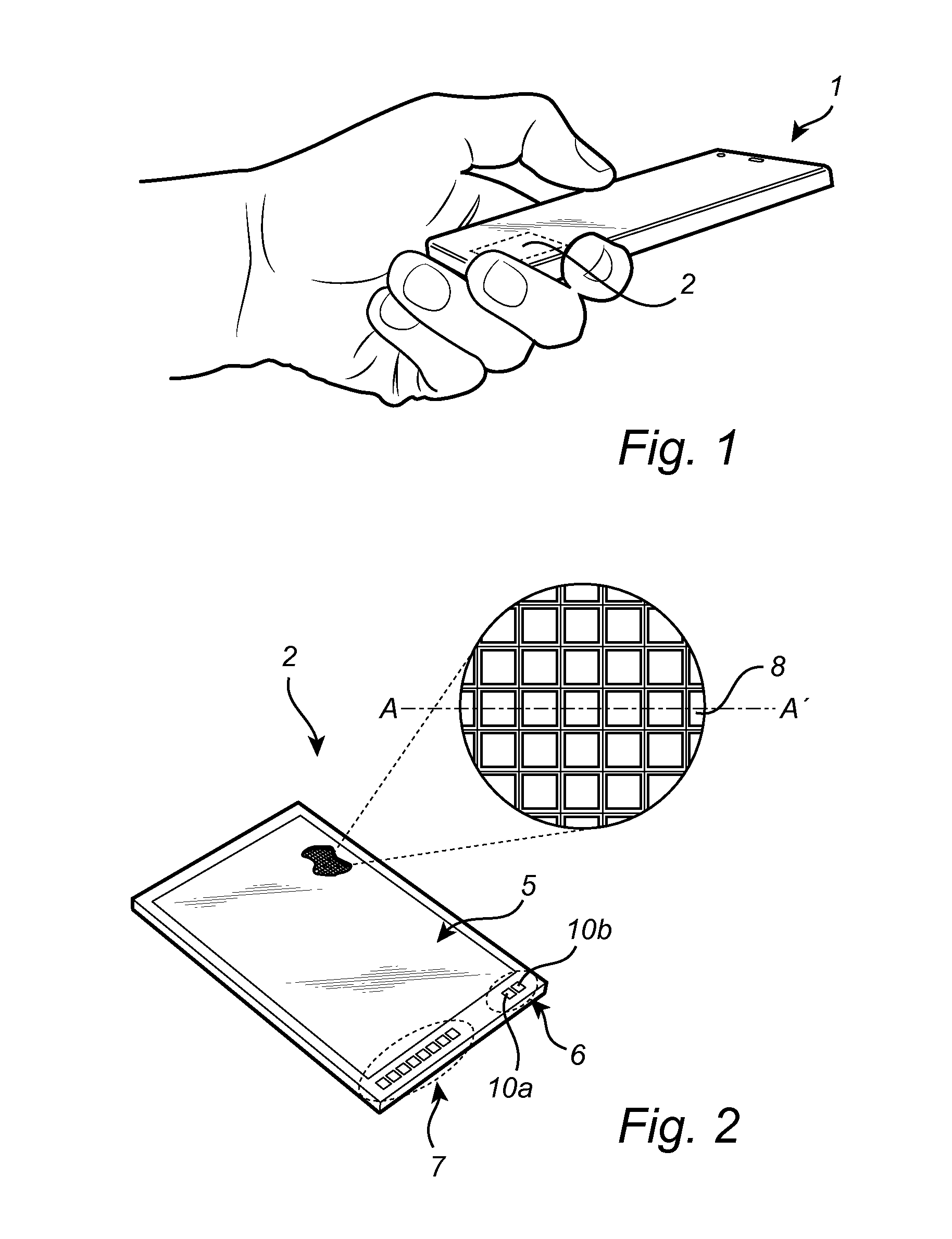
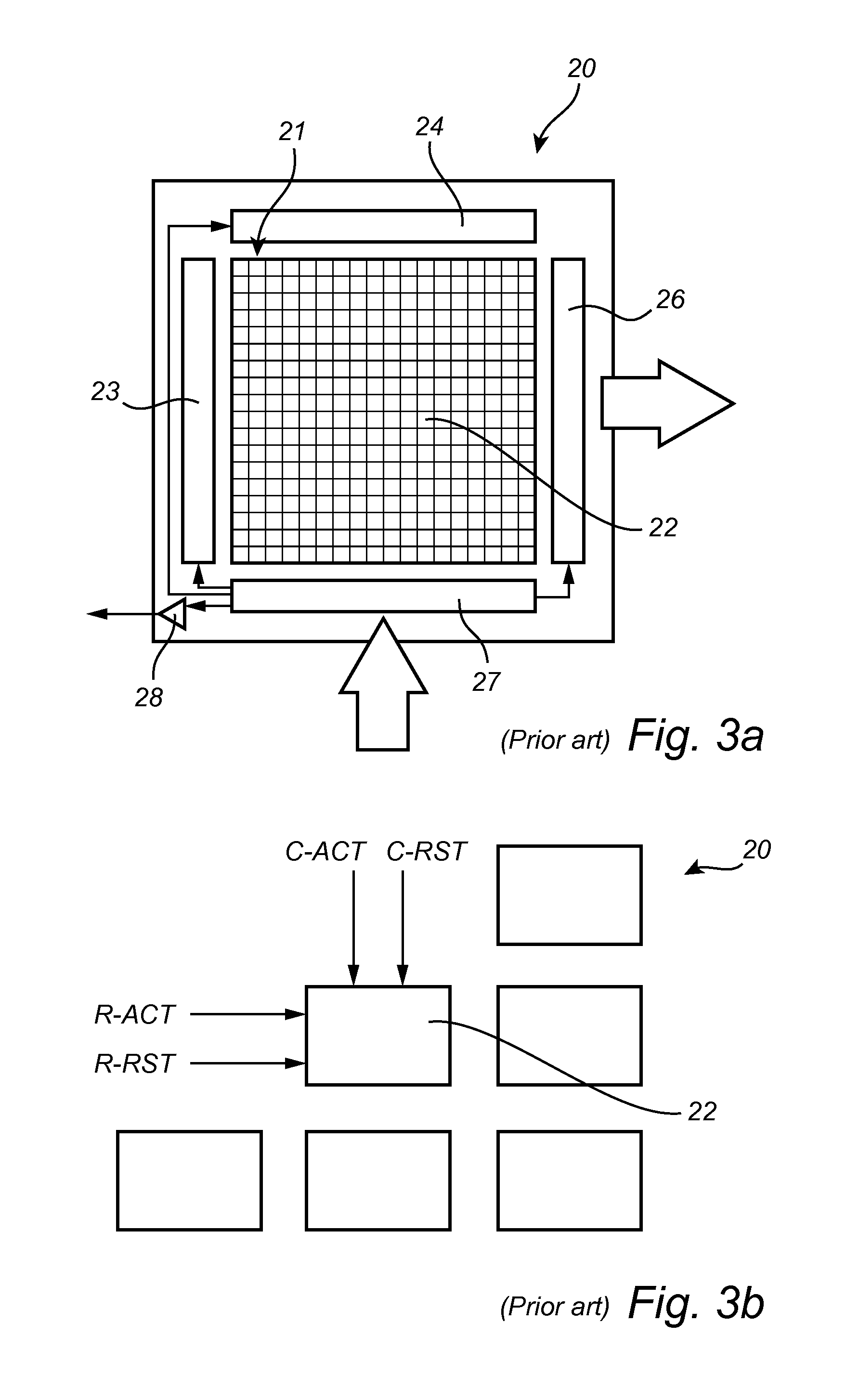
[0078]In the present detailed description, various embodiments of the fingerprint sensing device and method according to the present invention are mainly described with reference to a capacitive fingerprint sensing device, in which each sensing element comprises charge measuring circuitry including a charge amplifier for measuring charge carried by the sensing structure, excitation signal providing circuitry for providing an excitation or drive signal to the sensing structure and timing circuitry comprising a plurality of delay elements for controlling operation of the charge amplifier and the excitation signal providing circuitry. Moreover, the capacitive fingerprint sensing device is illustrated as a touch sensor dimensioned and configured to acquire a fingerprint representation from a stationary finger.

[0079]It should be noted that this by no means limits the scope of the present invention, which equally well includes, for example, a capacitive fingerprint sensing device includin...


PUM


Abstract

The present invention relates to a capacitive fingerprint sensing device for sensing a fingerprint pattern of a finger, the capacitive fingerprint sensor comprising a plurality of sensing elements, each including: a protective dielectric top layer to be touched by the finger; an electrically conductive sensing structure arranged underneath the top layer; charge measuring circuitry connected to the sensing structure for sequentially transitioning between at least a first measurement state and a second measurement state to perform a measurement sequence resulting in an output signal from the charge measuring circuitry being indicative of a change of a charge carried by the sensing structure resulting from a change in a potential difference between the finger and the sensing structure; and timing circuitry connected to the charge measuring circuitry for controlling a timing of at least one of the measurement states.

Description

CROSS-REFERENCE TO RELATED APPLICATIONS[0001]This application claims the benefit of Swedish Patent Application No. 1451633-0, filed Dec. 22, 2014. The disclosure of the above application is incorporated herein by reference in its entirety.FIELD OF THE INVENTION[0002]The present invention relates to a capacitive fingerprint sensing device and to a method of sensing a fingerprint pattern.BACKGROUND OF THE INVENTION[0003]Various types of biometric systems are used more and more in order to provide for increased security and / or enhanced user convenience.[0004]In particular, fingerprint sensing systems have been adopted in, for example, consumer electronic devices, thanks to their small form factor, high performance and user acceptance.[0005]Among the various available fingerprint sensing principles (such as capacitive, optical, thermal etc), capacitive sensing is most commonly used, in particular in applications where size and power consumption are important issues.[0006]All capacitive ...

Claims


Application Information

Patent Timeline
IPC IPC(8): G06K9/00G01N27/22G06V40/13
CPCG01N27/22G06K9/0002A61B2562/0214G06V40/1329G06V40/1306G01R27/2605G06F3/03547G07C9/00
Inventor RIEDIJK, FRANK ROBERT
Owner FINGERPRINT CARDS ANACATUM IP AB
Learn More