
Switching power supply and method for controlling voltage of bulk capacitor in the same

Active Publication Date: 2016-06-23
DELTA ELECTRONICS INC
View PDF18 Cites 11 Cited by
  • Summary
  • Abstract
  • Description
  • Claims
  • Application Information

AI Technical Summary

Benefits of technology

The patent discusses the miniaturization of switching power supplies. However, as the frequency of switching increases, a bigger volume of magnetic elements is required. In AC input applications, a bulk capacitor is used to balance input and output powers, but this cannot be reduced in size as the frequency increases. This results in a bigger proportion of the volume of the switching power supply being occupied by the bulk capacitor, which hinders the miniaturization of the switching power supply. The technical effect of the patent is to address this issue and allow for the miniaturization of switching power supplies with higher switching frequencies.

Problems solved by technology

As a result, as the switching frequency increases, volume of the Bulk capacitor occupies a growing proportion in the volume of a switching power supply, which becomes a bottleneck of the miniaturization of switching power supplies.

Method used


Image

  • Switching power supply and method for controlling voltage of bulk capacitor in the same
  • Switching power supply and method for controlling voltage of bulk capacitor in the same
  • Switching power supply and method for controlling voltage of bulk capacitor in the same

Examples


Embodiment Construction

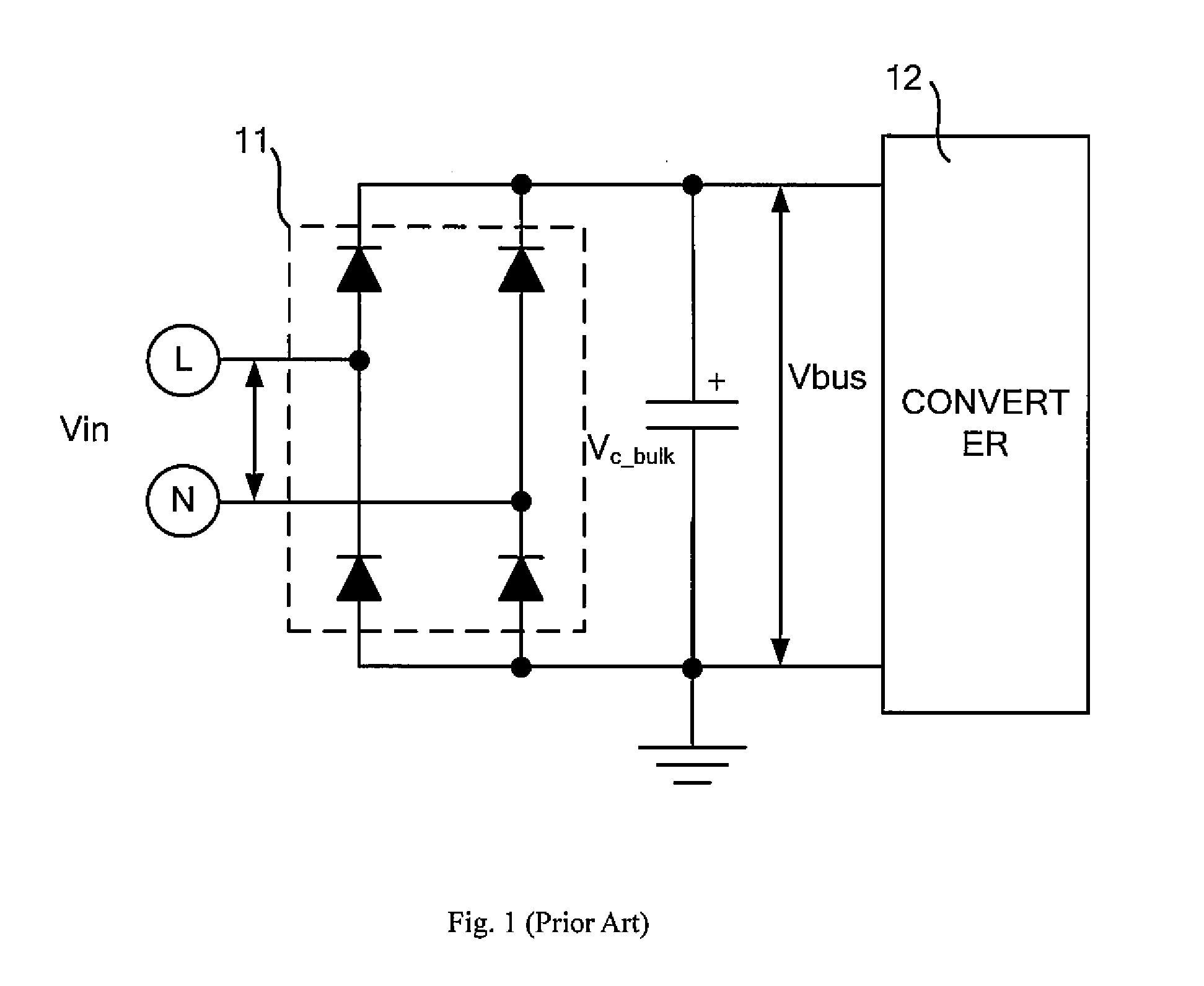
[0015]FIG. 1 illustratively shows a circuit diagram of a conventional switching power supply. In the switching power supply, a Bulk capacitor C_bulk is connected in parallel with a rectifier bridge 11 and a converter 12 in a subsequent stage. The Bulk capacitor C_bulk may be charged by a voltage rectified by the rectifier bridge 11, and may in turn provide power to the converter 12 in a subsequent stage.

[0016]A Bulk capacitor in a switching power supply, as shown in FIG. 1, performs a function of balancing the instantaneous input and output powers under AC mains frequency, and thus the Bulk capacitor cannot be miniaturized as the switching frequency increases. As a result, as the switching frequency increases, the volume of a Bulk capacitor occupies a growing proportion in the volume of a switching power supply, which becomes a bottleneck of the miniaturization of switching power supplies.

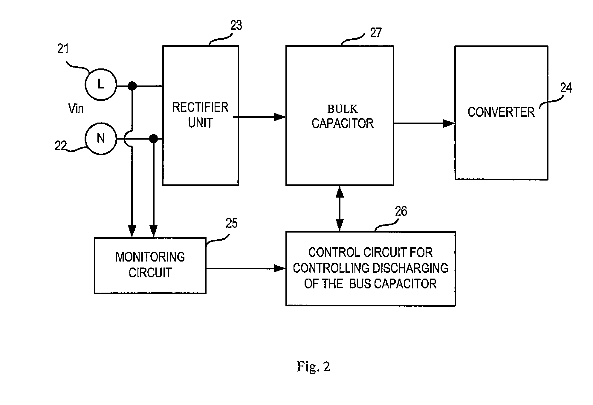
[0017]FIG. 2 illustratively shows a circuit block diagram of a switching power supply according...


PUM


Abstract

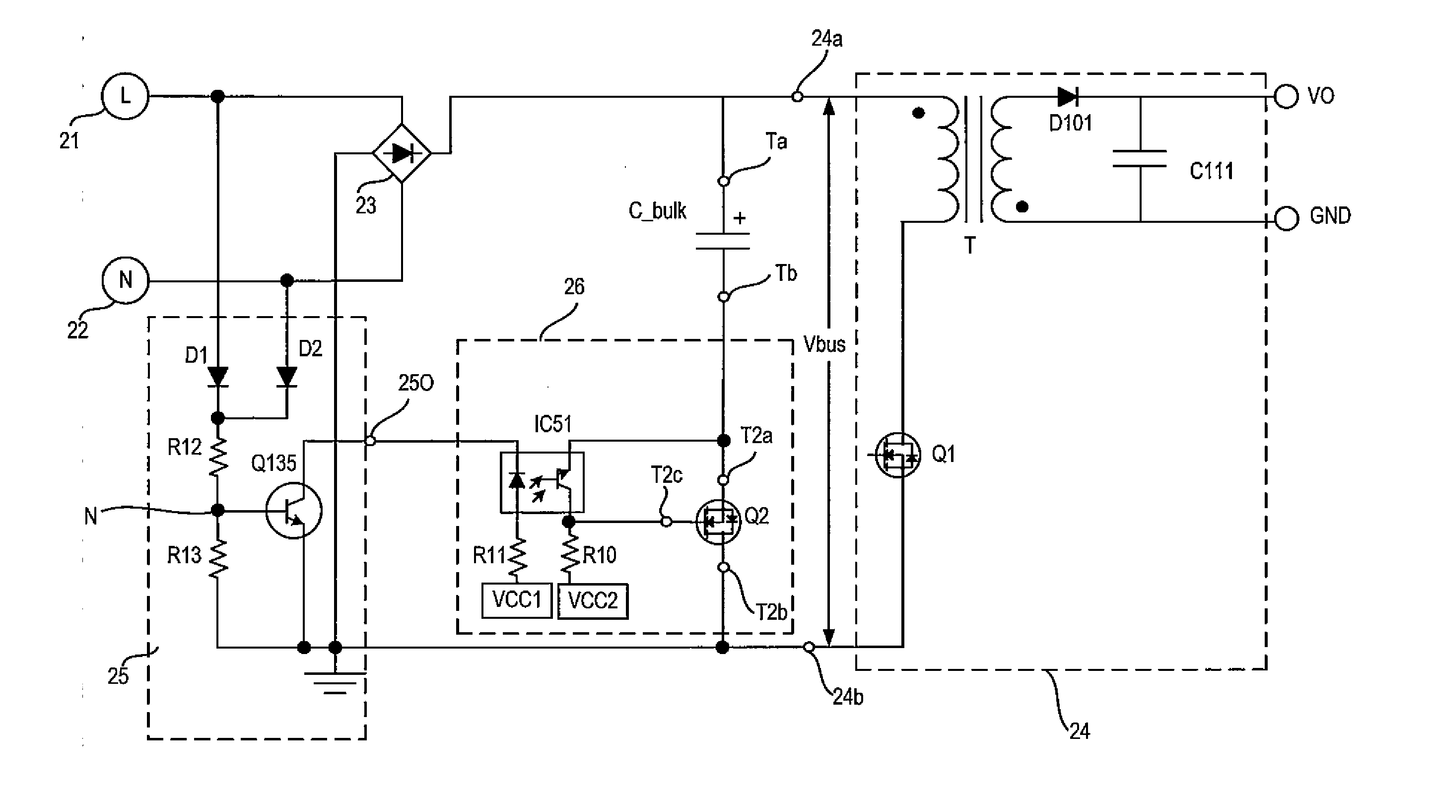
A switching power supply and a method for controlling a voltage of a Bulk capacitor in the switching power supply are provided. The switching power supply includes: a rectifying unit; a Bulk capacitor; a converter; a monitoring circuit; a control circuit, controlling discharging of the Bulk capacitor, being configured to perform controls such that the voltage across the Bulk capacitor maintains the peak value after the Bulk capacitor having been charged to a peak value of AC voltage, and to perform controls such that the Bulk capacitor discharges from a peak value when the instantaneous absolute value of the AC voltage is smaller than or equal to the preset voltage. Using the technical solution of the present disclosure, a discharging time of the Bulk capacitor can be shortened, and thereby the volume of the Bulk capacitor is reduced. Consequently, it is conducive to realize miniaturization of the switching power supply.

Description

[0001]This application is based upon and claims priority to Chinese Patent Application No. 201410794862.6, filed on Dec. 18, 2014, the entire contents of which are incorporated herein by reference.TECHNICAL FIELD[0002]The present disclosure relates to the technical field of switching power supplies.BACKGROUND[0003]In recent years, switching power supplies are developing to be miniaturized. Following such a development, switching power supplies are designed with higher switching frequency, and thus the volume of magnetic elements in the switching power supplies can be reduced. For Alternating Current (AC) input application, there is usually a Bulk capacitor to balance the instantaneous input and output powers under line frequency, and thus the Bulk capacitor cannot be miniaturized as the switching frequency increases. As a result, as the switching frequency increases, volume of the Bulk capacitor occupies a growing proportion in the volume of a switching power supply, which becomes a...

Claims


Application Information

Patent Timeline
IPC IPC(8): H02M3/335H02M1/00
CPCH02M3/33507H02M1/15H02M3/335H02M7/06H02M1/007
Inventor SONG, HAIBINXU, DAOFEI
Owner DELTA ELECTRONICS INC
Learn More