X-ray CT apparatus and image reconstruction method

a technology of which is applied in the field of x-ray ct apparatus and image reconstruction method, can solve the problems of deteriorating spatial resolution and improving spatial resolution around the center so as to improve spatial resolution of the entire effective field of view, improve spatial resolution, and reduce rotational speed

Active Publication Date: 2016-06-30
FUJIFILM HEALTHCARE CORP
View PDF1 Cites 2 Cited by
  • Summary
  • Abstract
  • Description
  • Claims
  • Application Information

AI Technical Summary

Benefits of technology

[0009]The present invention can provide an X-ray CT apparatus and an image reconstruction method that can improve spatial resolution of the entire effective field of view without reducing a rotational speed in the FFS method for improving spatial resolution by moving an X-ray focal spot to a plurality of positions to acquire projection data.

Problems solved by technology

By the way, there is a problem that spatial resolution around the center of the entire effective field of view is improved while the spatial resolution deteriorates in the peripheral portion other than the central portion in an image reconstructed using the conventional FFS method.

Method used


Image

  • X-ray CT apparatus and image reconstruction method
  • X-ray CT apparatus and image reconstruction method
  • X-ray CT apparatus and image reconstruction method

Examples


first embodiment

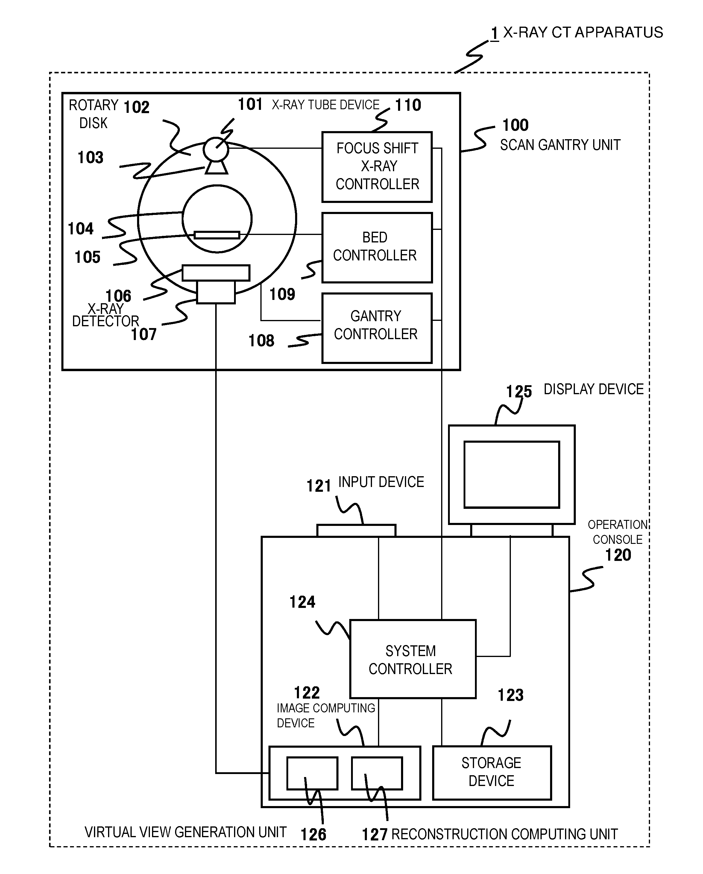
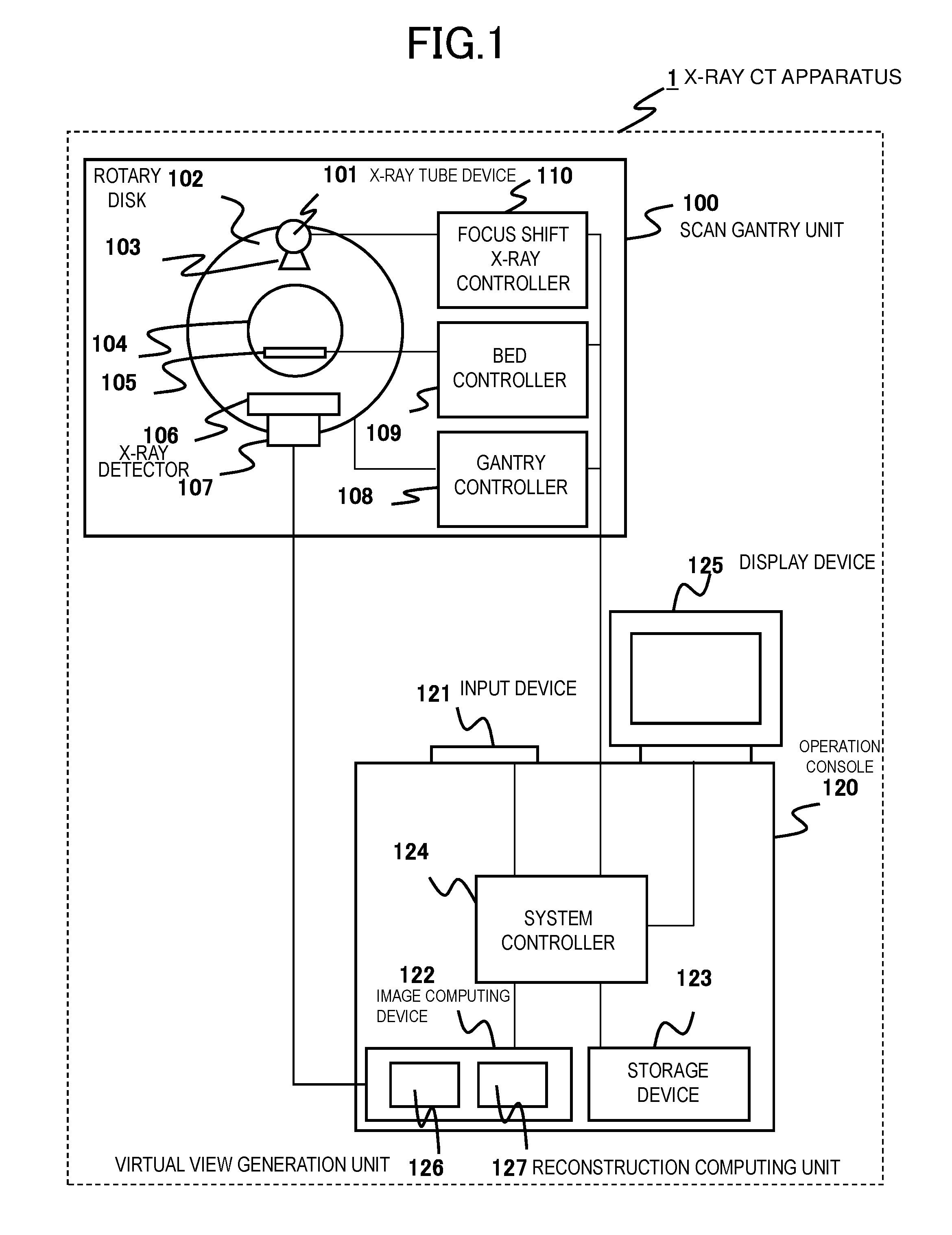
[0036]First, referring to FIG. 1, the overall configuration of the X-ray CT apparatus 1 will be described.

[0037]As shown in FIG. 1, the X-ray CT apparatus 1 is provided with the scan gantry unit 100 and the operation console 120.

[0038]The scan gantry unit 100 is a device for irradiating an X-ray to an object and detecting the X-ray transmitted through the object and is comprised of the X-ray tube device 101, the rotary disk 102, the collimator 103, the X-ray detector 106, the data collection device 107, the gantry controller 108, the bed controller 109, and the focal shift X-ray controller 110.

[0039]The rotary disk 102 is provided with the opening 104, and the X-ray tube device 101 and the X-ray detector 106 are disposed oppositely across the opening 104. An object placed on the bed 105 is inserted in the opening 104. The rotary disk 102 rotates around the object using the driving force to be transmitted through the driving transmission system from the rotary disk driving device con...

second embodiment

[0111]Next, the second embodiment of the present invention will be described referring to FIGS. 16 to 18.

[0112]The X-ray CT apparatus 1 of the second embodiment performs the joint process so that spatial resolution continues smoothly at the boundary point P0 in the reconstruction computing process.

[0113]In the joint process, as shown in FIG. 16, both an image reconstructed by FFS projection data and an image reconstructed by up-sampled projection data are synthesized at a predetermined rate in a region of a predetermined range including the boundary point P0 (hereinafter, referred to as the boundary region Q). In the central region 604a closer to the center than the boundary region Q, an image reconstructed by actual data of FFS projection data is used 100% similarly to the first embodiment. In the peripheral region 603a outside the boundary region Q, an image reconstructed by up-sampled projection data is used 100% similarly to the first embodiment.

[0114]That is, according to the d...

third embodiment

[0129]Next, referring to the FIGS. 19 and 20, the third embodiment of the present invention will be described.

[0130]In the X-ray CT apparatus 1 of the third embodiment, it may be configured so that an image using actual data of FFS projection data and an image using up-sampled projection data are synthesized by changing weight over the entire image.

[0131]FIG. 19 is a graph showing the weighting factor W′(P) to be applied to a reconstruction image by up-sampled projection data in the third embodiment. This graph rises smoothly from “0” in a region close to the center and becomes “1” at the end of the peripheral region. That is, the graph has a shape in which a weighting factor changes according to the distance from the center O even in a region other than the boundary region Q. Thus, the graph shape of the weighting factor may be arbitrary, the weighting factor is changed so as to acquire desired spatial resolution in a desired region even in a region other than the boundary region Q...


PUM


Abstract

In an FFS method that improves spatial resolution by moving an X-ray focal spot to multiple positions to acquire projection data, in order to provide an X-ray CT apparatus and an image reconstruction method that enables to improve spatial resolution of the entire effective field of view without reducing a rotational speed, the X-ray focal spot in the X-ray tube device 101 is shifted to acquire focal shift projection data (FFS projection data), the virtual view generation unit 126 up-samples the FFS projection data (generates a virtual view) in the view direction, and the reconstruction computing unit 127 reconstructs an image using actual data of the FFS projection data in the central region 604 closer to the image center than a predetermined boundary and using the up-sampled projection data in the peripheral region 603 outside the boundary in an image reconstruction computing process.

Description

TECHNICAL FIELD[0001]The present invention relates to an X-ray CT apparatus and an image reconstruction method, and in detail, to an image reconstruction method suitable for an X-ray CT apparatus using an X-ray tube device that can irradiate X-rays from a plurality of focal spots.BACKGROUND ART[0002]An X-ray CT apparatus is an apparatus in which an X-ray tube device and an X-ray detector are oppositely disposed to rotate around an object, irradiates X-rays from a plurality of rotation angle directions (views) to detect the X-ray transmitted through the object for each view, and generate a tomographic image of the object based on the detected projection data. In the recent years, an FFS (Flying Focal Spot) X-ray tube device having a function to irradiate X-rays to a plurality of spots by shifting an X-ray focus has been developed. In the FFS X-ray tube device, an X-ray focal spot can be shifted to a plurality of positions by electromagnetically moving a position of an electronic beam...

Claims


Application Information

Patent Timeline
Patent Type & Authority Applications(United States)
IPC IPC(8): A61B6/00G06T11/00A61B6/03
CPCA61B6/5205A61B6/032G06T11/005A61B6/4435A61B6/4021A61B6/465A61B6/467A61B6/469G06T3/4069G06T11/006
Inventor FUJII, HIDEAKINAKAZAWA, TETSUO
Owner FUJIFILM HEALTHCARE CORP
Why Eureka
Try Eureka