
Nozzle for connecting or disconnecting solder joints between head bonding pads in a hard disk drive, and laser soldering or reflowing tool with the same

a technology for connecting or disconnecting solder joints and head bonding pads, which is applied in the direction of manufacturing tools, non-electric welding apparatus, and soldering apparatus, etc., can solve the problems of reducing precision and alignment of soldering, increasing the difficulty of laser bonding between the bonding pads, and reducing the structure. compactness, high speed connection

Active Publication Date: 2016-06-30
SAE MAGNETICS (HK) LTD
View PDF4 Cites 4 Cited by
  • Summary
  • Abstract
  • Description
  • Claims
  • Application Information

AI Technical Summary

Benefits of technology

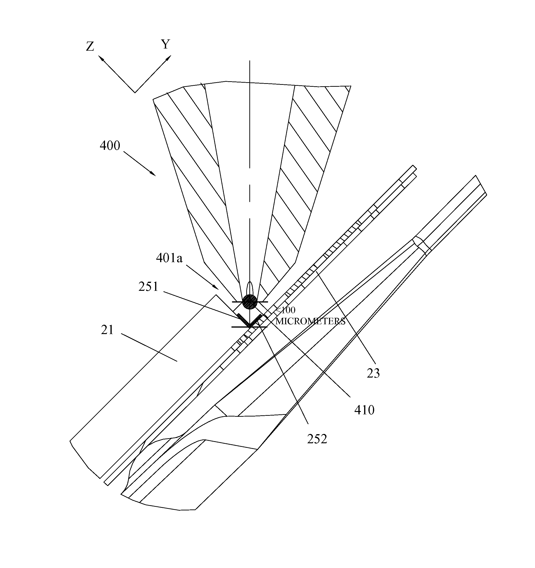
The present invention provides a nozzle for connecting or disabling solder joints between head bonding pads of a hard disk drive, which avoids interference between the tip of the nozzle and elements adjacent to the slider during the soldering operation, and maintains a safe and suitable clearance to achieve high precision and high speed connection or disconnection of solder joints. The interference-free structure of the nozzle tip reduces the width and outer circumference of the tip compared to prior art without damaging the central duct. This improves the safety and alignment for soldering or reflowing, increases the assembly efficiency and yield for the hard disk drive, and saves assembly or manufacturing cost.

Problems solved by technology

Nowadays, as the demands for excellent performance for the sliders become more and more higher, the slider and its accessorial elements are increased, which requires the structure become much compact.
By this token, such accessorial elements bring the complicated HGA, which increases difficulty for laser bonding between the bonding pads of the slider and the suspension, or solder reflowing operation.
To avoid it, the solder-jet nozzle 170 has to be moved far away from the slider 11 during bonding, which reduces the precision and alignment for soldering and reducing the assembly yield however.
Specially, the disadvantages are even obvious for fine-pitch bonding pads connection (11 or 13 pads).

Method used


Image

  • Nozzle for connecting or disconnecting solder joints between head bonding pads in a hard disk drive, and laser soldering or reflowing tool with the same
  • Nozzle for connecting or disconnecting solder joints between head bonding pads in a hard disk drive, and laser soldering or reflowing tool with the same
  • Nozzle for connecting or disconnecting solder joints between head bonding pads in a hard disk drive, and laser soldering or reflowing tool with the same

Examples


Embodiment Construction

[0049]Various preferred embodiments of the invention will now be described with reference to the figures, wherein like reference numerals designate similar parts throughout the various views. As indicated above, the invention is directed to a solder-jet nozzle, a solder-reflow nozzle and a laser soldering or reflowing tool for connecting or disconnecting solder joints between head bonding pads of a head gimbal assembly for a hard disk drive, which avoids interference between the tip of the nozzle and elements adjacent to the slider during the soldering operation, and maintains a safe and suitable clearance to obtain high precision and high speed connection or disconnection of solder joints.

[0050]In this invention, the interference-free structure configured on the tip of the nozzle body is adapted for both solder-jet nozzle and solder-reflow nozzle, and the details will be described, infra. The nozzle according to the present invention is not only applicable to connect or disconnect ...


PUM

PropertyMeasurementUnit
angleaaaaaaaaaa
angleaaaaaaaaaa
depthaaaaaaaaaa

Abstract

A nozzle for connecting or disconnecting solder joints between head bonding pads of in a hard disk drive, includes a nozzle body including a tip, the tip disposed at a distal end of the nozzle body and configured to deliver or reflow a solder ball in proximity to head bonding pads; and a central duct disposed along a central axis of the nozzle body and configured to convey the solder ball to or from the tip. The tip includes a front face facing to a trailing edge of a slider, a back face facing to a top surface of a suspension supporting the slider, and two side faces adjacent to the front face and back face respectively, and at least one interference-free structure is provided at two adjacent faces of the tip at least, thereby no interference happens between the tip and elements adjacent to the slider during the operation.

Description

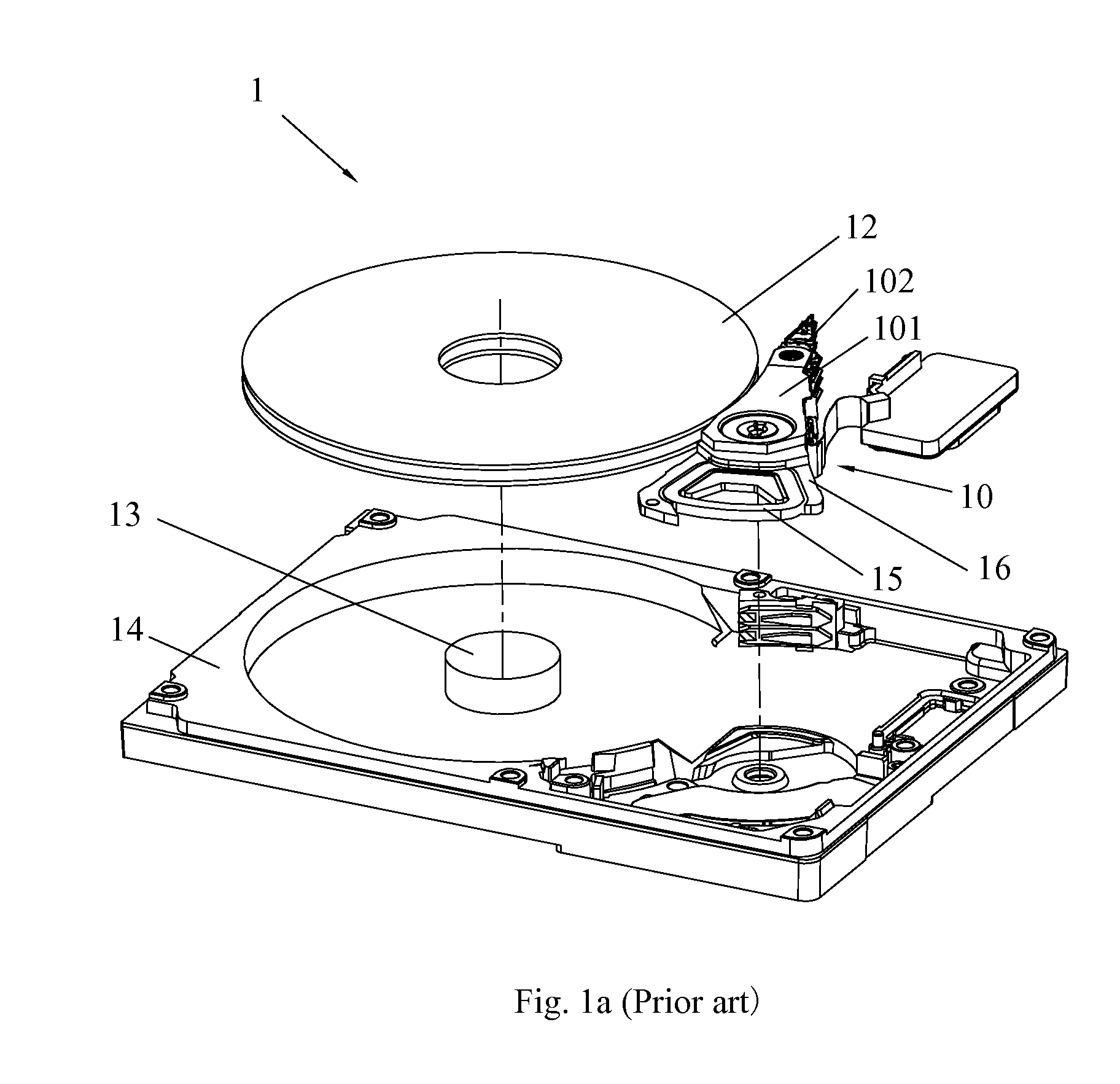
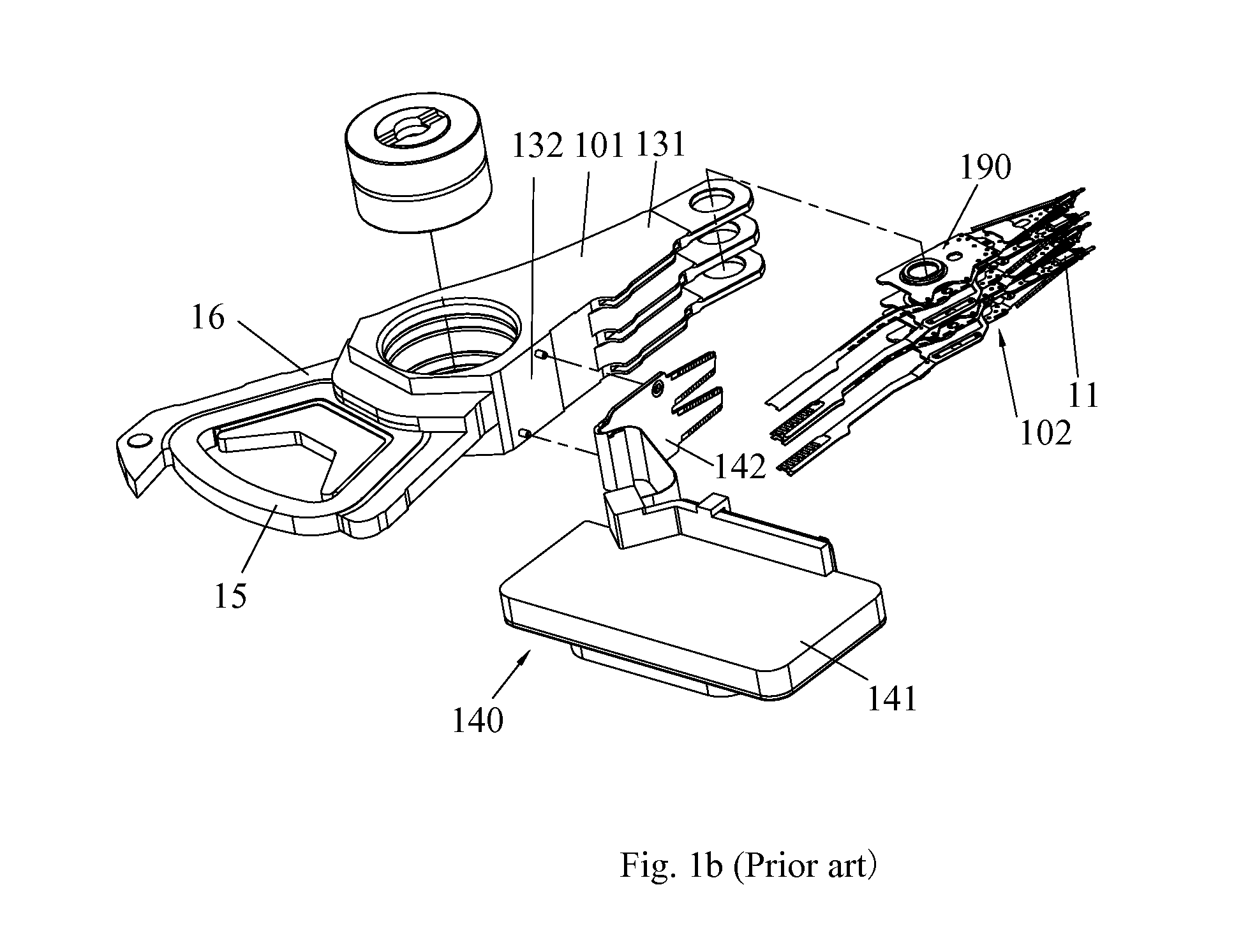
FIELD OF THE INVENTION[0001]The present invention relates to a nozzle for connecting or disconnecting solder joints between head bonding pads in a hard disk drive and, more particularly, to a solder-jet nozzle or a solder-reflow nozzle for solder joints between head bonding pads of a head gimbal assembly (HGA) for a hard disk drive (HDD).BACKGROUND OF THE INVENTION[0002]Hard disk drives are information storage devices that use thin film magnetic media to store data. Referring to FIG. 1a, a typical hard disk drive 1 in prior art comprises a head stack assembly (HSA) 10 with slider 11 (shown in FIG. 1b) thereon, a magnetic disk 12 mounted on a spindle motor 13 which causes the magnetic disk 12 to spin, and a motor base 14 to enclose the above-mentioned components.[0003]The slider 11 flies over the surface of the magnetic disk 12 at a high velocity to read data from or write data to concentric data tracks on the magnetic disk 12, which is positioned radially by a voice coil 15 embedded...

Claims


Application Information

Patent Timeline
Patent Type & Authority Applications(United States)
IPC IPC(8): B23K3/06B23K1/00B23K1/005
CPCB23K3/0623B23K1/0008B23K1/0056
Inventor LO, CHIWAICHOU, SHENKUANGHO, YIUSINGWONG, KAYIPTAN, XIANGYUANZHANG, JUNQUN
Owner SAE MAGNETICS (HK) LTD
Learn More