Operating system utilizing an articulated bolt train to manage recoil force

a technology of operating system and recoil force, which is applied in the direction of weapons, butts, weapon components, etc., can solve the problems of ineffective volume and total weight of different means used to achieve recoil absorption, and no previous patent used active firing mechanisms,

Inactive Publication Date: 2016-06-30
PIZANO JORGE
View PDF6 Cites 19 Cited by
  • Summary
  • Abstract
  • Description
  • Claims
  • Application Information

AI Technical Summary

Benefits of technology

[0007]The Operating System presented in this Patent application is notoriously different than any other known art. The present invention has at least one the following advantages.
[0043]A transient Gyroscopic Effect or Angular Moment is generated in every shoot recoil motion by the angular motion of some of the train components, while transitioning from the bore axial path to the transverse path, in the curved zone of the path. This angular motion of the Firing Mechanism Carriage Subassembly is capable of compensating to some extent, the rotation reaction (Barrel Torque) effect of the barre...

Problems solved by technology

However, none of the previous patents uses the active firing mechanisms as part of the moving recoiling mass displacing transversally.
Nor it uses an active recoil damper mechanism.
However the different means used to achieve the recoil absorption are significantly inefficient in terms of the volume and total weight required.
None of the design solutions involve the use of firing mechanisms displacement or the use of the firing mechanisms mass as a part of the recoiling inertial mass.
It is notorious for being voluminous and unwieldy.
And furthermore, the array of mechanisms condemns the operation, in p...

Method used


Image

  • Operating system utilizing an articulated bolt train to manage recoil force
  • Operating system utilizing an articulated bolt train to manage recoil force
  • Operating system utilizing an articulated bolt train to manage recoil force

Examples


Embodiment Construction

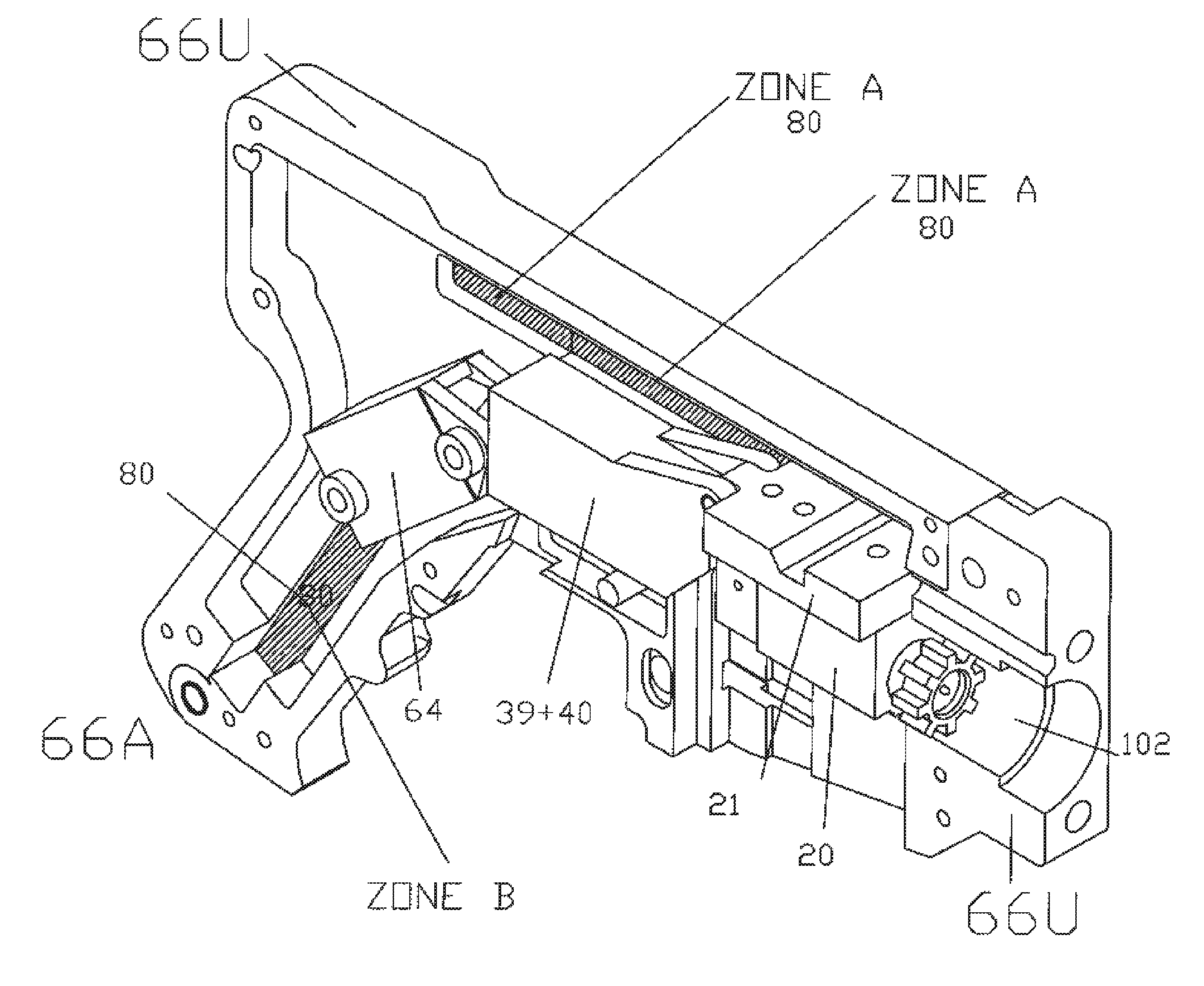
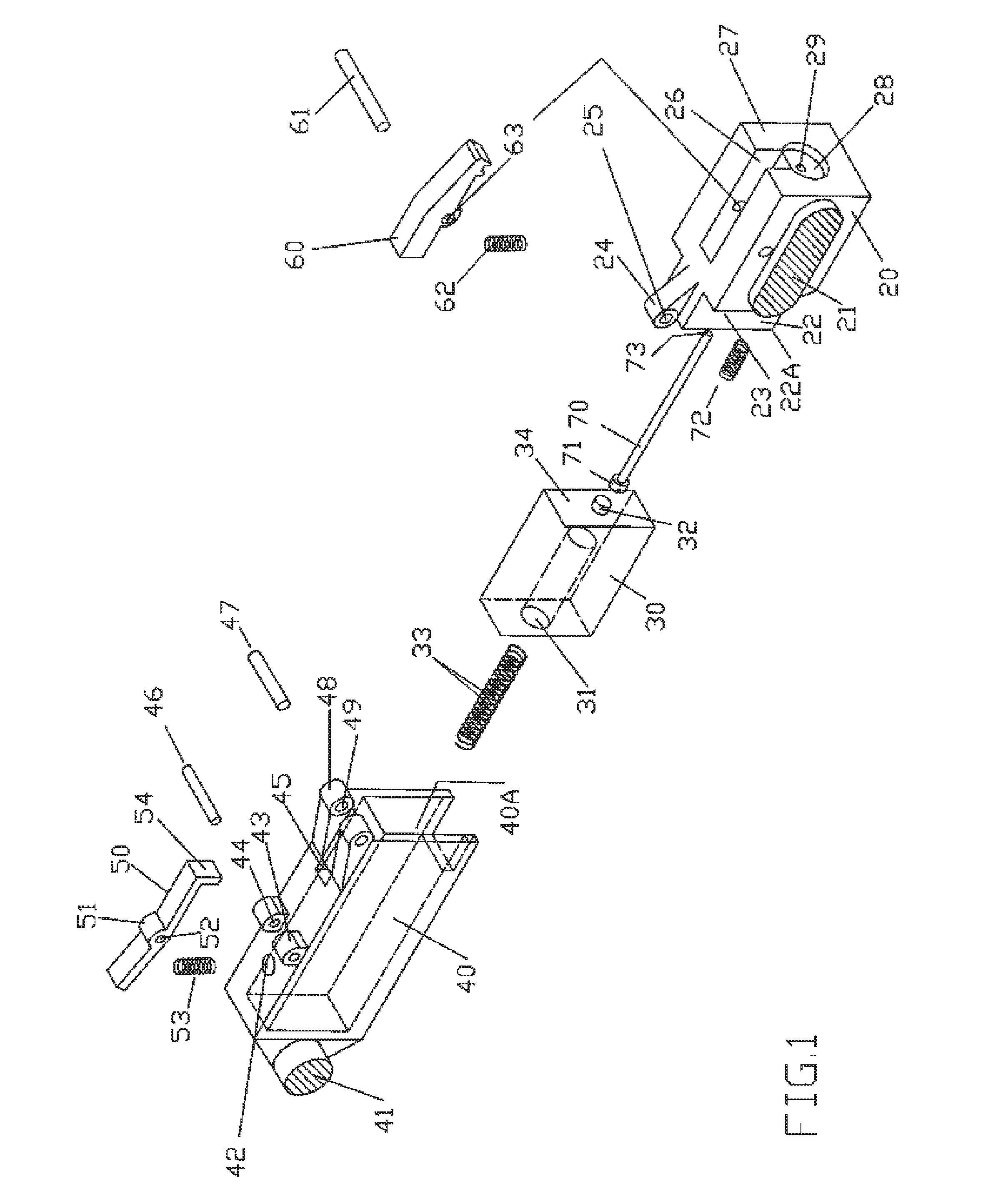
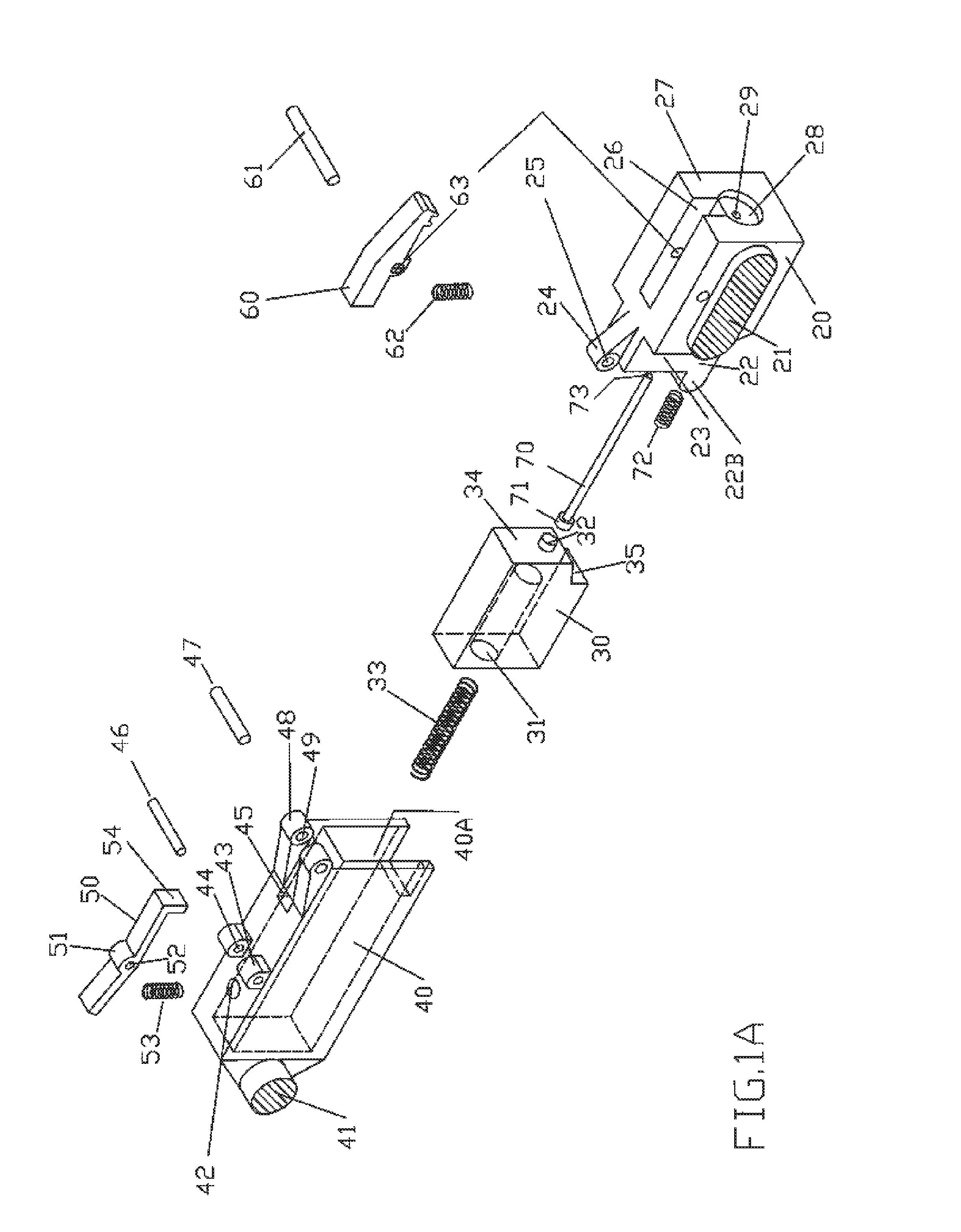
[0228]a. This invention presents a linearly displacing hammer. Similar results in terms of recoil absorption can be obtained by placing a compact array of firing mechanisms with conventional rotary parts behind the front bolt as a part of another type of traveling mechanisms carriage, however it would require more volume, which defeats the purpose of accommodating the traveling mechanisms in a tight space such as the inside of the handgrip.[0229]b. Additional recoil absorption can be achieved by placing conventional shock absorbers, hydraulic or pneumatic, rubber pads at the end of the cavity that receives the mechanisms carrier housing 40. Elastomeric shock absorber can be placed to additionally abate the recoil by allowing the recoiling mechanisms carrier housing 40 stop against them.[0230]c. Neither the mechanisms carrier cavity 40A, the hammer 30, nor the mechanism carriers housing 30 are necessarily rectangular. They are of the convenient shape to accommodate a convenient shape...


PUM

PropertyMeasurementUnit
Forceaaaaaaaaaa
Torqueaaaaaaaaaa
Dynamicaaaaaaaaaa

Abstract

An Operational System for Firearms founded on the use of the synchronic controlled motion and cooperative interaction of elements of a Pivotally Articulated Bolt Train displacing reciprocatingly within a compliant receiver, along guiding means, disposed according to a purposely engineered Path, capable of generating anticipated adjustable dynamic reactions, and to execute mechanical actions, due to pre-calculated movements of interconnecting mechanisms within said Train members, when they pivot one relative to the other. The alternate divergent and converging motion of the Train Bolt and A Firing Mechanism Carriage subassembly, along a horizontal path, and a transverse path, modifies and splits the linear bearing of the recoil force, and generates a Gyroscopic Effect or Angular Moment, decreasing the Barrel Torque magnitude, conveying a unique tailored dynamic behavior, while performing different functions and achieving the eleven different purposes of this invention. Numerous motion parameters are adjustable to attain the distinctive recoil Dynamic reaction.

Description

CROSS-REFERENCE TO RELATED APPLICATIONS[0001]This application is a Continuation-in-Part of co-pending U.S. patent application Ser. No. 13 / 385,262, filed on Feb. 2, 2012, which claims the benefit of Provisional Patent Application Ser. No. 61 / 463,034 filed on Feb. 11, 2011, now expired. The entirety of both the co-pending non-provisional and expired provisional applications are herein incorporated by reference.FIELD OF THE INVENTION[0002]This application relates generally to a firearm operational system improvement, describing an Articulated Bolt Train mechanism in which The Head Bolt moves linearly aligned with the axis of the barrel and the second train member, the Firing Mechanism Subassembly, may have a movement component perpendicular to the barrel axis in certain sectors of the Motion path when it changes the bearing, from horizontally aligned with the axis of the barrel, to a transverse, through the handle direction. This redirection of the path causes significant reaction forc...

Claims


Application Information

Patent Timeline
IPC IPC(8): F41A3/12F41A5/18
CPCF41A5/18F41A3/12F41A3/26F41A5/24Y10T29/49826F41A3/36F41C23/16
Inventor PIZANO, JORGE
Owner PIZANO JORGE
Why Eureka
Try Eureka