Circuit module system

a technology of circuit modules and circuit modules, applied in the field of circuit modules, can solve the problems of increasing manufacturing difficulties, affecting the use and teaching of students, and adding costs to magnets, and achieves the effects of low manufacturing costs, strong detachment, and easy design and manufactur

Inactive Publication Date: 2016-06-30
CUBEXUS LTD
View PDF4 Cites 12 Cited by
  • Summary
  • Abstract
  • Description
  • Claims
  • Application Information

AI Technical Summary

Benefits of technology

[0020]The exemplary embodiment of the present invention has the advantages, such as three dimensionally stacking and connecting, low manufacturing cost, easily design and manufacture, and strong detachment even hanging vertically. By the vertical stacking and lateral connection, the conventional serial connection which takes a lot of spaces can be prevented, and interfering with other adjacent element no longer exists. Due to varieties of combinations, new modules can easily to be developed to expend the circuit module system.

Problems solved by technology

However, since the connecting force of the magnets is limited, so the modules are easy to separate when there are plenty of circuit modules connected together, they always causes frustration in using and teaching.
Moreover, the magnets are a added cost and the magnets are disposed in a burying way, which increases the difficulties in manufacturing as well, i.e. low yield rate.
In addition, the aforementioned circuit module system can only serially connects the circuit module units, and the vertically stacking and side connection of the circuit modules cannot be achieved.
Therefore, the application and the variability are very limited.
Furthermore, with more and more circuit module units are connected, the space for placing those connected circuit modules is getting larger, which may take too many space in your creation.

Method used


Image

  • Circuit module system
  • Circuit module system
  • Circuit module system

Examples


Embodiment Construction

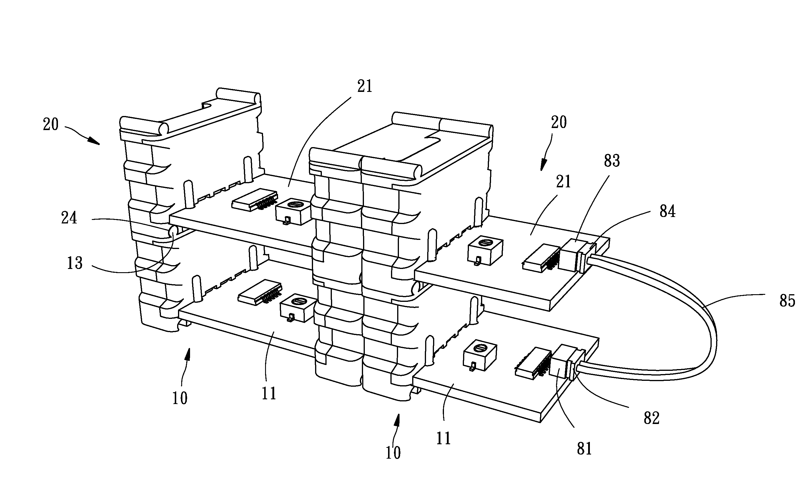
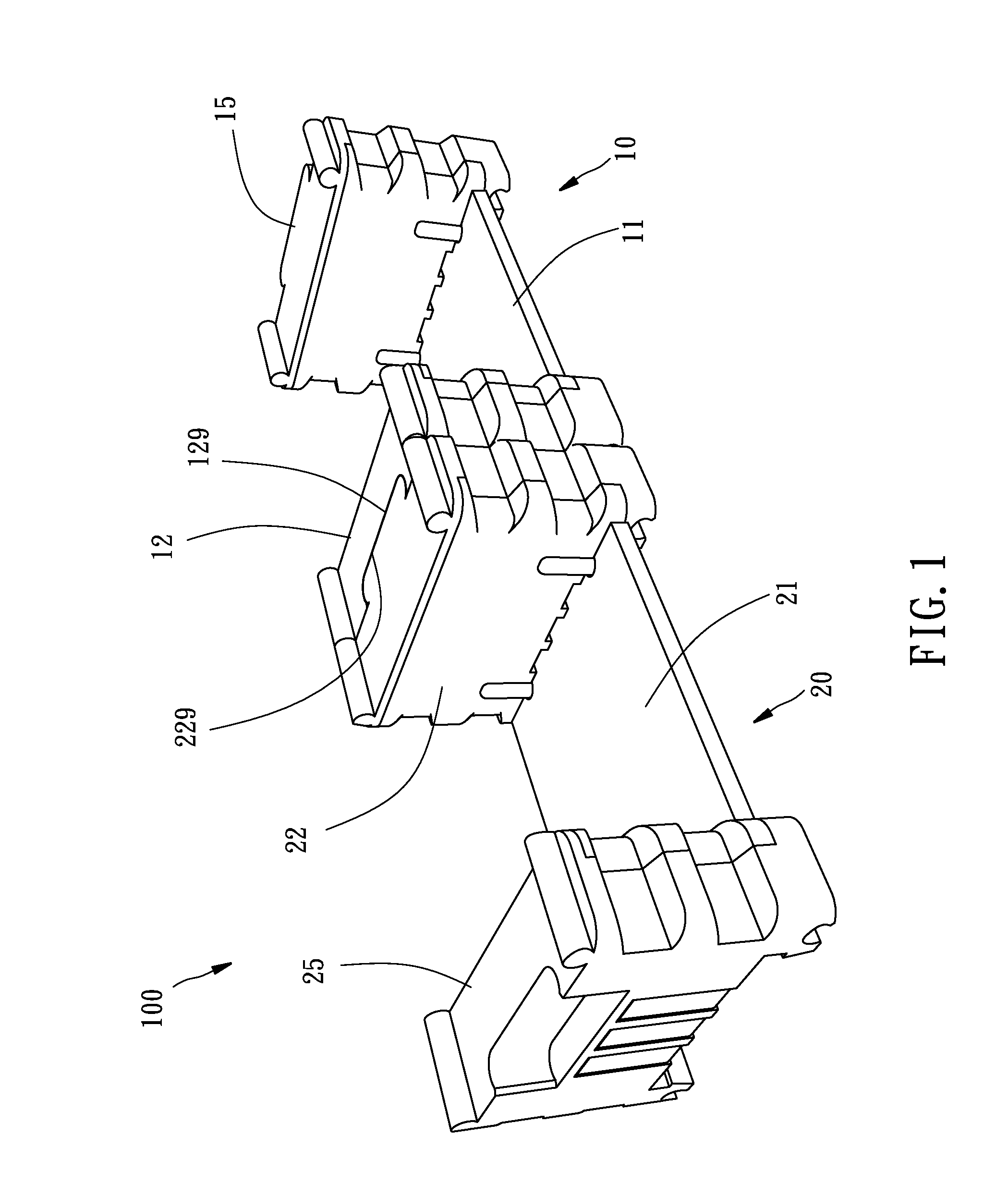
[0032]Referring to FIGS. 1-10, one of the exemplary embodiments of the present invention provides a circuit module system 100, which includes a first circuit module 10 and a second circuit module 20.

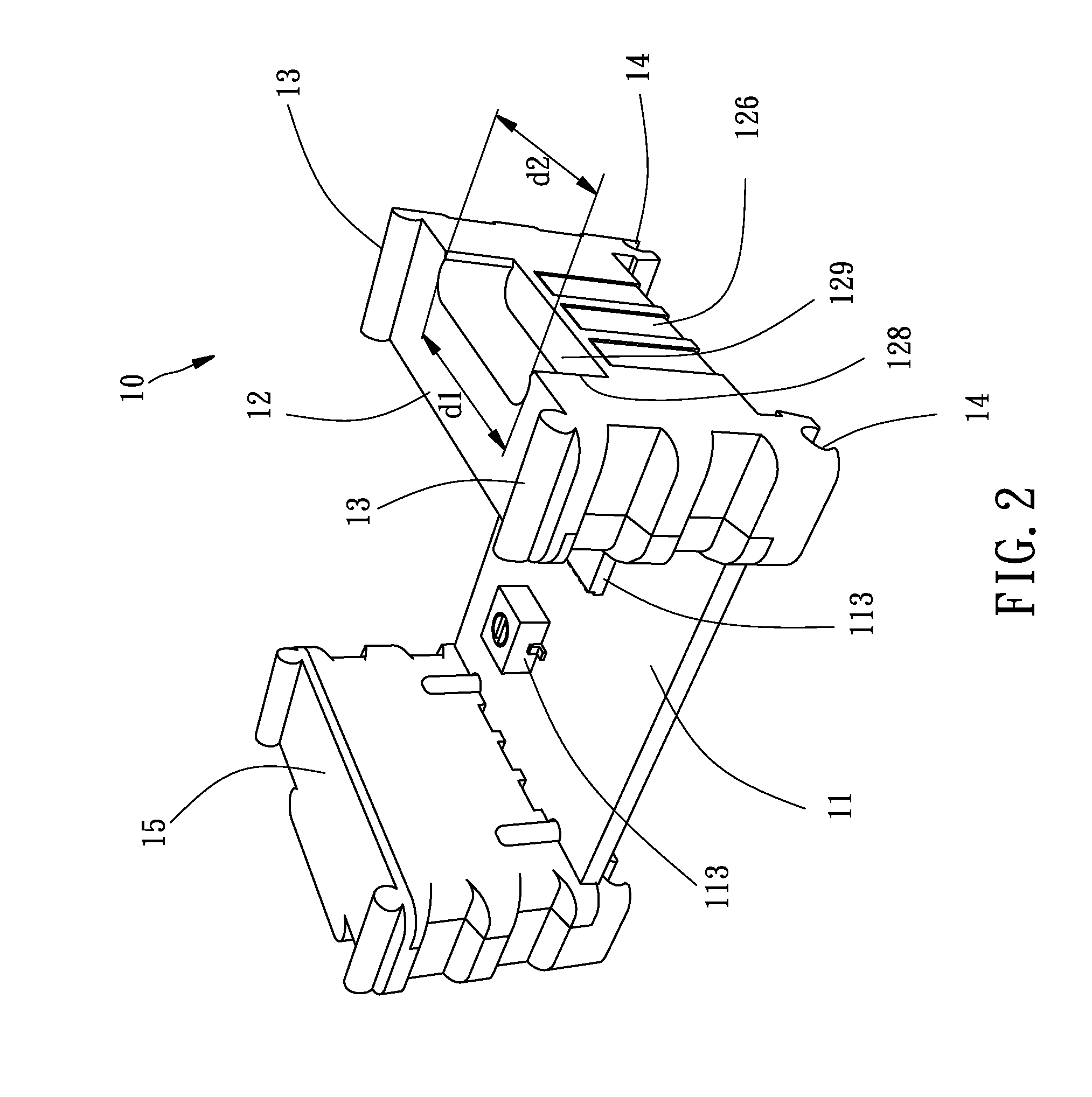
[0033]Referring to FIGS. 1-4, in one of the exemplary embodiments, the first circuit module 10 includes a first circuit board 11 and a first connecting housing 12. The first connecting housing 12 includes a first base 121 and at least one first conductor 122. The first base 121 is connected to one side of the first circuit board 11, and the at least one first conductor 122 is clamped on the first base 121. The first conductor 122 electrically connects the first circuit board 11 to outside.

[0034]In one of the exemplary embodiments, the first circuit board 11 is provided with a conductor circuit (not shown in the FIGS.) connecting electric component 113. The first circuit board 11 is provided with a connecting hole 111 and an electrical terminal hole 112. The electrical terminal hole 112 i...


PUM


Abstract

A circuit module system includes a first and a second circuit module, the first circuit module includes a first circuit board and a first connecting housing, the first connecting housing includes a first base connected to a side of the first circuit board and at least one first conductor. A top surface of the first base forms a fillister connecting to outside, the first conductor is clamped on the first base and electrically connects the first circuit board to outside. The second circuit module includes a second circuit board and a second connecting housing, the second connecting housing includes a second base connected to a side of the second circuit board and at least one second conductor. A protruding part protrudes from an outer side of the second base, the second conductor is clamped on the second base and electrically connects the second circuit board to outside.

Description

BACKGROUND[0001]1. Technical Field[0002]The technical field relates to a circuit module, particularly to a scalable stackable circuit module system where the circuit modules are not easy to detach from one another.[0003]2. Related Art[0004]The US patent US 2013 / 0343025 A1 discloses the most common circuit module system used for teaching purpose, and a plurality of circuit modules can be connected by serial connection. The connection way of this patent provides magnets on ends of each of the circuit modules, and those circuit modules are connected by the magnets.[0005]However, since the connecting force of the magnets is limited, so the modules are easy to separate when there are plenty of circuit modules connected together, they always causes frustration in using and teaching.[0006]Moreover, the magnets are a added cost and the magnets are disposed in a burying way, which increases the difficulties in manufacturing as well, i.e. low yield rate.[0007]In addition, the aforementioned c...

Claims


Application Information

Patent Timeline
Patent Type & Authority Applications(United States)
IPC IPC(8): H05K1/14H01R12/71
CPCH01R12/718H05K1/144H01R9/2408H01R9/2458H01R12/732H05K1/142H05K1/184H05K2201/10189H05K2201/2072H05K2201/209
Inventor HUANG, SHENG-CHELIU, YU-TSEHU, WEI-HANLEE, CHIEN-HUNG
Owner CUBEXUS LTD
Why Eureka
Try Eureka