Liquid ejecting head and manufacturing method thereof
- Summary
- Abstract
- Description
- Claims
- Application Information
AI Technical Summary
Benefits of technology
Problems solved by technology
Method used
Image

Examples
first embodiment
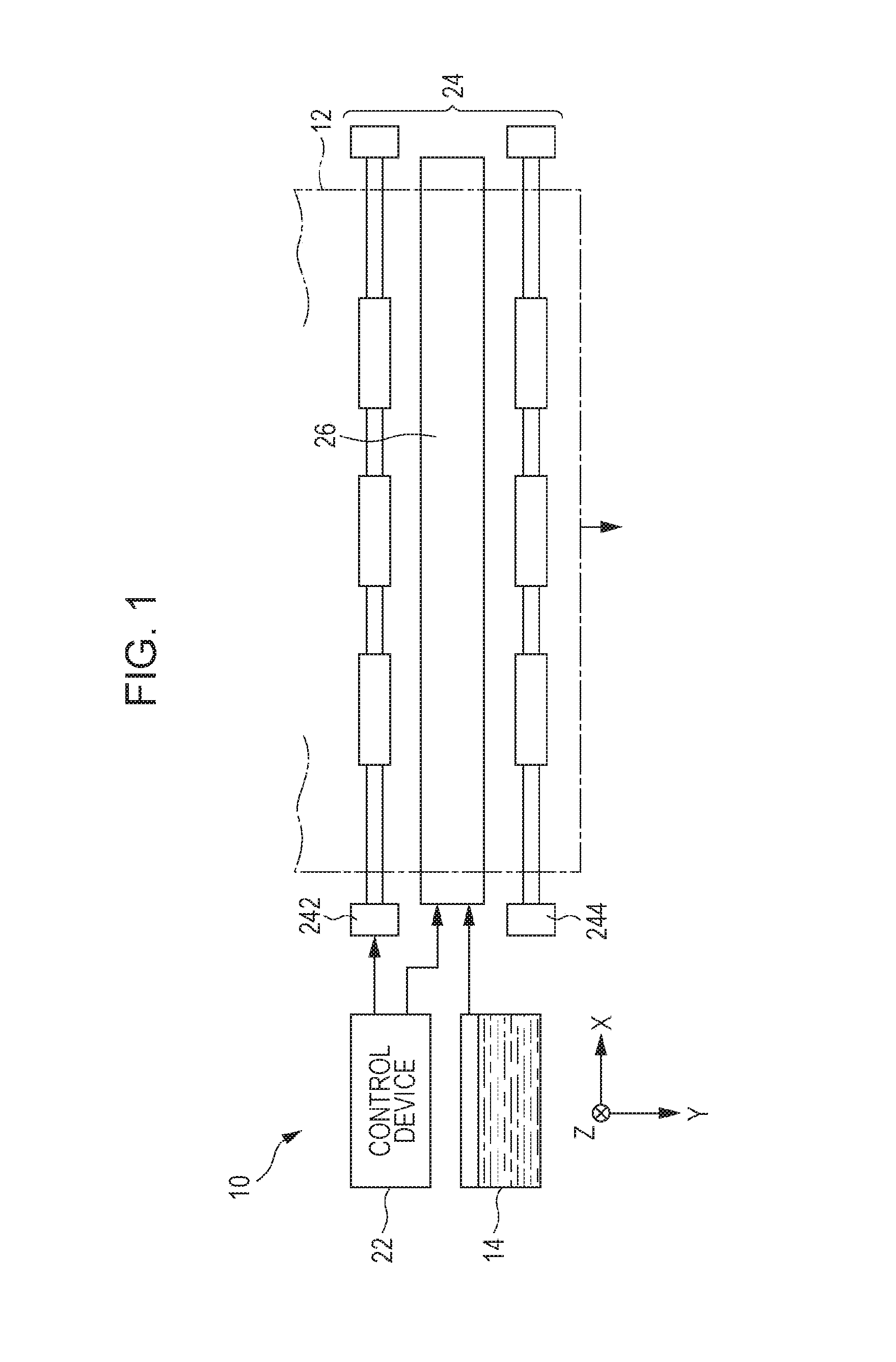
[0049]First, a liquid ejecting apparatus according to a first embodiment of the invention will be described by taking an ink jet type printing apparatus as an example. FIG. 1 is a partial configuration view of an ink jet type printing apparatus 10 according to the first embodiment of the invention. The printing apparatus 10 of the first embodiment is a liquid ejecting apparatus ejecting ink that is an example of a liquid onto a medium (ejection target) 12 such as a printing sheet and includes a control device 22, a transport mechanism 24, and a liquid ejecting unit 26. A liquid container (cartridge) 14 for storing the ink is mounted on the printing apparatus 10.
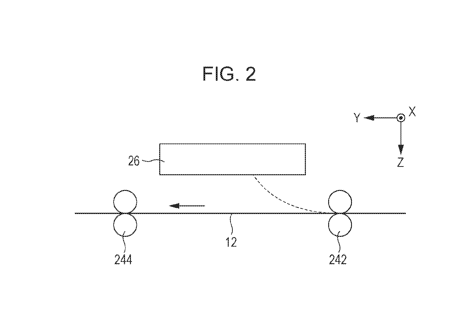
[0050]The control device 22 collectively controls each element of the printing apparatus 10. The transport mechanism 24 transports the medium 12 in a Y-direction under the control of the control device 22. FIG. 2 is a configuration view of the printing apparatus 10 that focuses on the transport of the medium 12. As illustrate...
second embodiment
[0108]A second embodiment of the invention will be described below. Moreover, in each aspect illustrated below, the same reference numerals using in the description of the first embodiment are given to elements, of which effects and functions are the same as those of the first embodiment, and detailed description of each element will be omitted.
[0109]FIGS. 16A and 16B are explanatory views describing a relationship between a fixing plate 38 and a liquid ejection section 32 in the second embodiment and correspond to FIGS. 7A and 7B in the first embodiment. FIG. 16A is a sectional view that is taken along line XVIA-XVIA of the fixing plate 38 illustrated in FIG. 6 and FIG. 16B is a sectional view of a case where the liquid ejection section 32 is fixed to the fixing plate 38. Similar to drawing, punching for forming an opening section 52 in the flat plate is also a type of press processing and the opening section 52 is formed by disposing a dies on one surface of the flat plate and all...
third embodiment
[0123]A third embodiment of the invention will be described below. FIGS. 20A and 20B are views illustrating a configuration example of a liquid ejecting head 30 according to the third embodiment. Here, as another configuration example of the liquid ejecting head 30 capable of applying a forming method of the protrusion section 60 by the first embodiment described above, a specific example of a case where the protrusion section 60 is formed in consideration of a region allowing a sealing mechanism (cap) 28 to abut a fixing plate 38 for preventing drying of nozzles N and the like is exemplified.
[0124]In FIG. 20A, a plan view of a second surface Q2 of the fixing plate 38 and a cross section view of line XXB-XXB are described together. As will be understood from the sectional view of FIG. 20B, the sealing mechanism 28 includes a plurality of sealing bodies 282 which seal each nozzle N by coming into contact with the second surface Q2 (liquid ejection surface) of the fixing plate 38 when...
PUM
| Property | Measurement | Unit |
|---|---|---|
| Thickness | aaaaa | aaaaa |
| Height | aaaaa | aaaaa |
Abstract
Description
Claims
Application Information
PatSnap Eureka turns technology decisions into work you can execute. Powered by our Innovation Knowledge Graph, it runs expert workflows across engineering, life sciences, materials and intellectual property. Get your review-ready output in minutes.


