Vehicular wind power generator

Inactive Publication Date: 2016-07-07
HU SUEY YUEH
View PDF5 Cites 12 Cited by
  • Summary
  • Abstract
  • Description
  • Claims
  • Application Information

AI Technical Summary

Benefits of technology

The present invention is suitable for electric and hybrid vehicles that need more power to travel longer distances. It increases the vehicle's efficiency by using longer blades that can catch more wind, which in turn increases the speed of the rotor and improves power generation.

Problems solved by technology

While the prior-art device is substantially a wind power generator, its closed structure is less effective.
Moreover, the rotating member is not designed to effectively collect and leverage the incoming wind to rotate at the possibly maximum speed, so the overall power-generating efficiency is poor.
However, the prior-art device is bulky and, when installed on a roof of a vehicle, tends to cause the vehicle to fail to meet traffic regulations about height, and endanger the vehicle when passing through tunnels and traffic signs due to the height that exceeds the safe height limit.

Method used


Image

  • Vehicular wind power generator
  • Vehicular wind power generator
  • Vehicular wind power generator

Examples


first embodiment

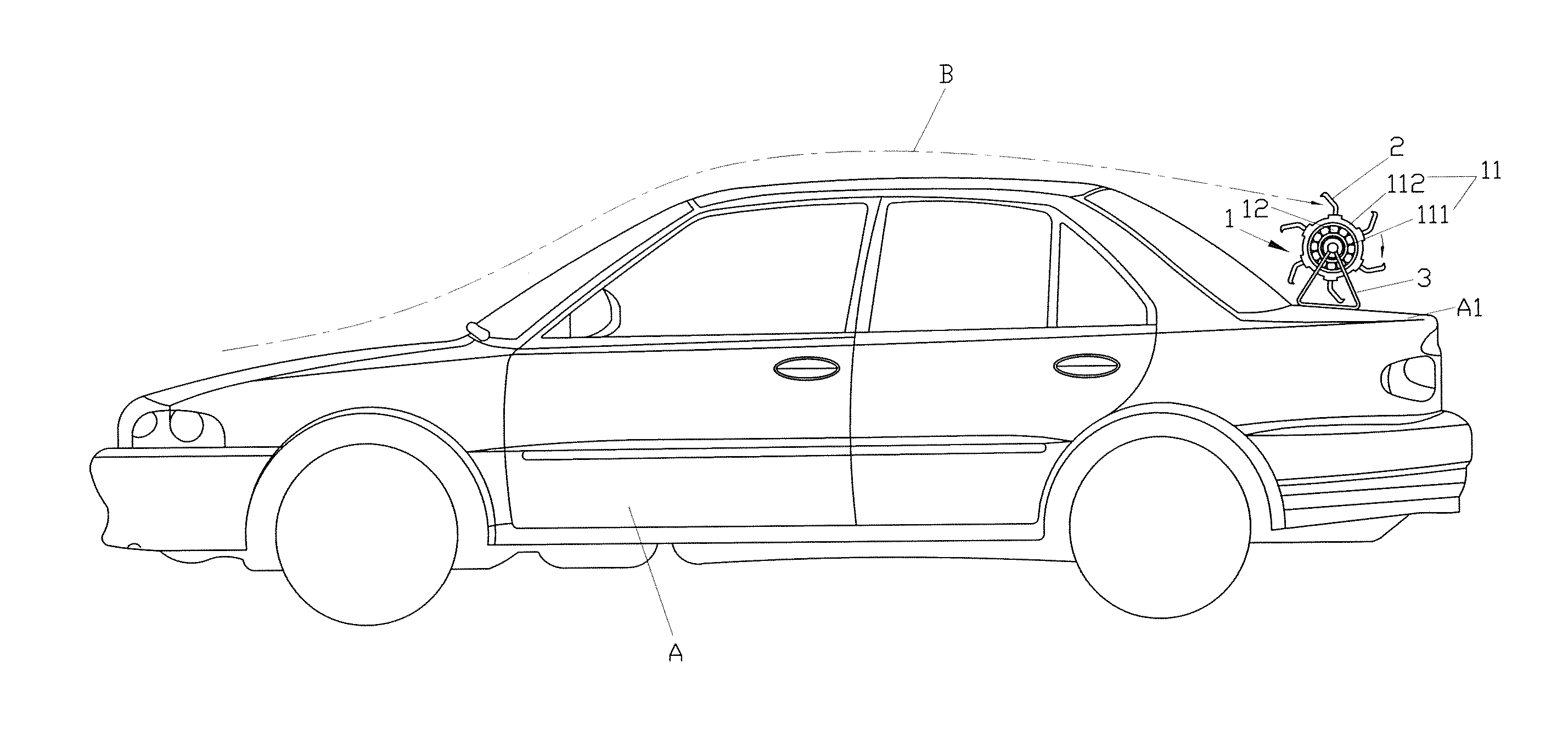
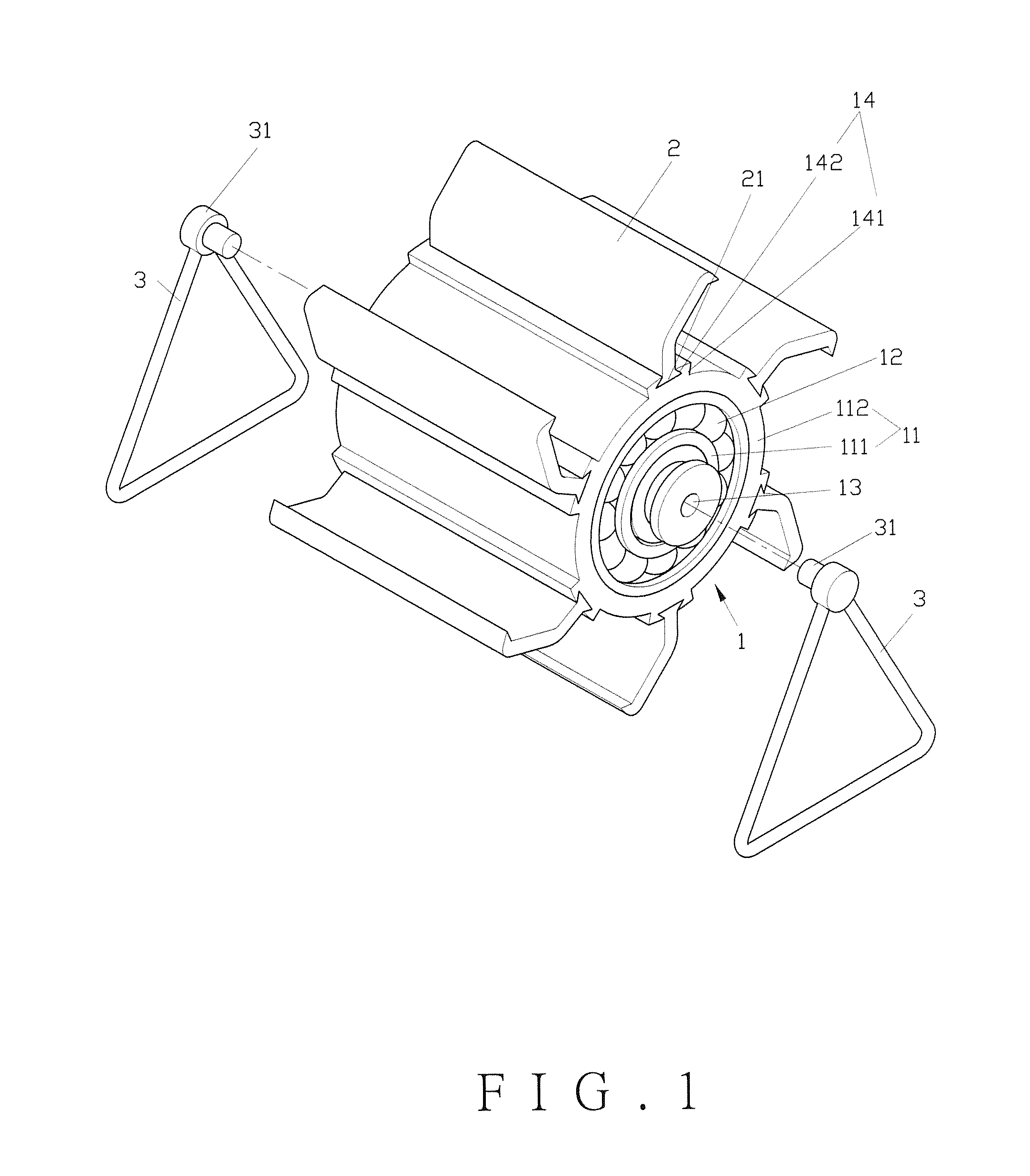
[0041]Referring to FIG. 1, FIG. 2 and FIG. 3, in the present invention, a vehicular wind power generator for being installed on a vehicle comprises a main body (1), a plurality of blades (2) and two stands (3).

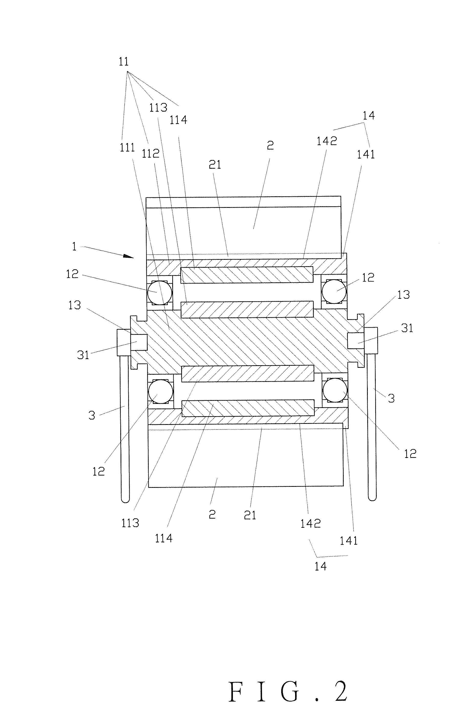
[0042]The main body (1) has a power-generating unit (11). The power-generating unit (11) has a stator (111) and a rotor (112) rotating with respect to each other. Between the stator (111) and the rotor (112) there is a bearing (12). The stator (111) is peripherally provided with a plurality of induction windings (113). The rotor (112) has a plurality of magnets (114). The main body (1) has two opposite ends each being provided with an axle portion (13). The main body (1) is peripherally provided with a plurality of combining portions (14). Each of the combining portions (14) comprises a ridge (141) raised from the periphery of the rotor (112). The ridge (141) is formed with a groove (142). In the present embodiment, the groove (142) has a dovetailed sectional shape.

[0043]The b...

second embodiment

[0047]Referring to FIG. 6 and FIG. 7, in the present invention, a vehicular wind power generator comprises a main body (1A), a plurality of blades (2A), a maglev unit (4A), and two stands (3A).

[0048]The second embodiment is different from the first embodiment in that each of the grooves (142A) has a doubly dovetailed sectional shape, and each of the wedges of the engaging portion (21A) also has a doubly dovetailed sectional shape matching that of the groove (142A), so the replacement of the blades (2A) is more convenient and the combination between the grooves (142A) and the engaging portions (21A) is more reliable.

[0049]Each of the blades (2A) comprises a first blade (22A), a second blade (23A), and a pivot portion (24A). The first blade (22A) and the second blade (23A) are connected to the pivot portion (24A). In the present embodiment, the pivot portion (24A) is a hinge, so that the first blade (22A) and the second blade (23A) are pivotable with respect to each other and retain e...


PUM


Abstract

A vehicular wind power generator for being installed on a vehicle includes a main body, multiple blades, two stands assembled to the main body, and a maglev unit. The main body has a power-generating unit including a stator and a rotor, between which a bearing is provided. The stator and the rotor are rotatable with respect to each other, and are provided with multiple induction windings and multiple magnets respectively. The blades are assembled to combining portions peripherally provided on the main body. The maglev unit includes first and second magnetic portions provided on the stator and the blades respectively and causing magnetic induction therebetween to generate repulsion. Thereby when the vehicle is moving, wind is guided to the blades so as to make the rotor rotate with respect to the stator, and cause the induction windings and the magnets to generate electric power due to electromagnetic effects.

Description

BACKGROUND OF THE INVENTION[0001]1. Technical Field[0002]The present invention relates to a vehicular wind power generator, which generates electrical power from wind when a vehicle carrying the same is moving.[0003]2. Description of Related Art[0004]Wind power is known as a kind of green energy resources. When a vehicle moves, air flows along its contours to form wind. Thus, it is desirable to leverage the wind to generate power and charge electric vehicles and hybrid vehicles so as to make the vehicle travel further as compared to its original capacity.[0005]Taiwan Patent No. M378970 provides a vehicular power system using wind power generation. The vehicular power system includes at least one box installed on a vehicle. The box has its front side formed with a wind inlet and its back side formed with a wind outlet. A rotating member provided in the box has a shaft terminally equipped with a wind power generator. The power generator is connected through a lead to a rectifier, whic...

Claims


Application Information

Patent Timeline
IPC IPC(8): F03D9/00F03D3/00
CPCF03D3/002F03D9/002F05B2240/215F05B2240/941F03D9/32Y02E10/74Y02E10/728F03D9/25F03D80/70
Inventor HU, SUEY-YUEH
Owner HU SUEY YUEH
Why Eureka
Try Eureka