
Blow Down Actuator Assembly

a technology of actuators and assemblies, applied in the direction of pyrotechnical actuators, belts/chains/gearings, etc., can solve the problems of requiring additional space and hardware, and failure of mechanical linear drive systems can have catastrophic consequences

Active Publication Date: 2016-07-07
AEROCONTROLEX GROUP
View PDF2 Cites 27 Cited by
  • Summary
  • Abstract
  • Description
  • Claims
  • Application Information

AI Technical Summary

Benefits of technology

The present invention provides an actuation assembly that includes an actuation member, a release member, and a source of pressurized gas. During normal operation, the actuation member and the release member move in unison. However, in an emergency mode, the pressurized gas automatically decouples the actuation member from the release member to move separately. The invention also includes an electro-mechanical actuator that includes an electro-mechanical drive system and an integrated backup system operated by a gas generator. When the backup system is activated, the electro-mechanical drive system is decouled, and the actuator moves to a predetermined position and mechanically locks in place. The invention allows for emergency situations to be addressed without causing damage or injury.

Problems solved by technology

Particularly in aeronautical applications, the failure of a mechanical linear drive system can have catastrophic consequences.
The failure of one or more aspects of the drive system, such as the motor, the gear train, or the ball screw drive, may result, for example, in the landing gear of an airplane failing to extend or to extend into a fully locked open position.
However, these systems are often separate assemblies from the drive assembly, requiring additional space and hardware to accommodate the assembly.

Method used


Image

  • Blow Down Actuator Assembly
  • Blow Down Actuator Assembly
  • Blow Down Actuator Assembly

Examples


Embodiment Construction

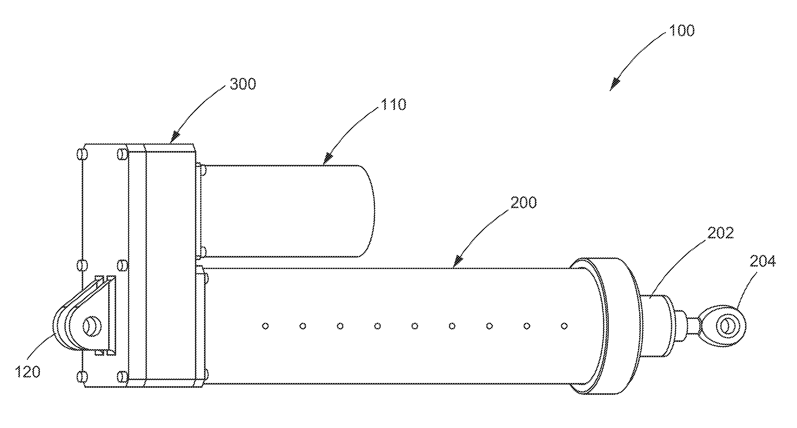
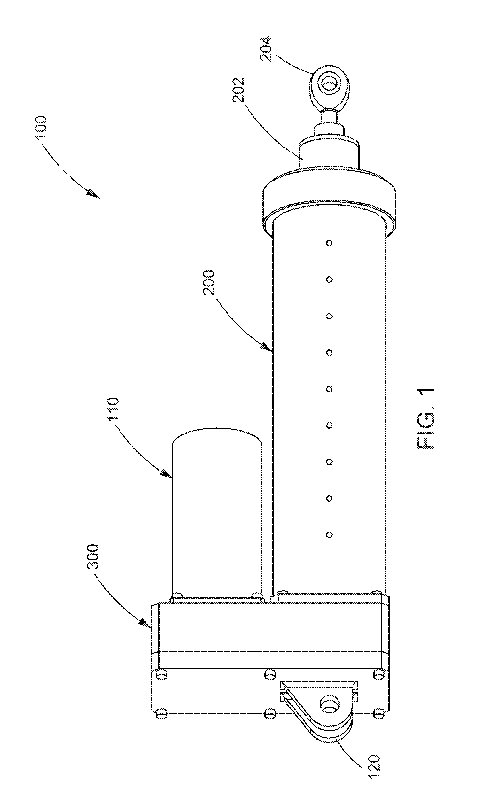
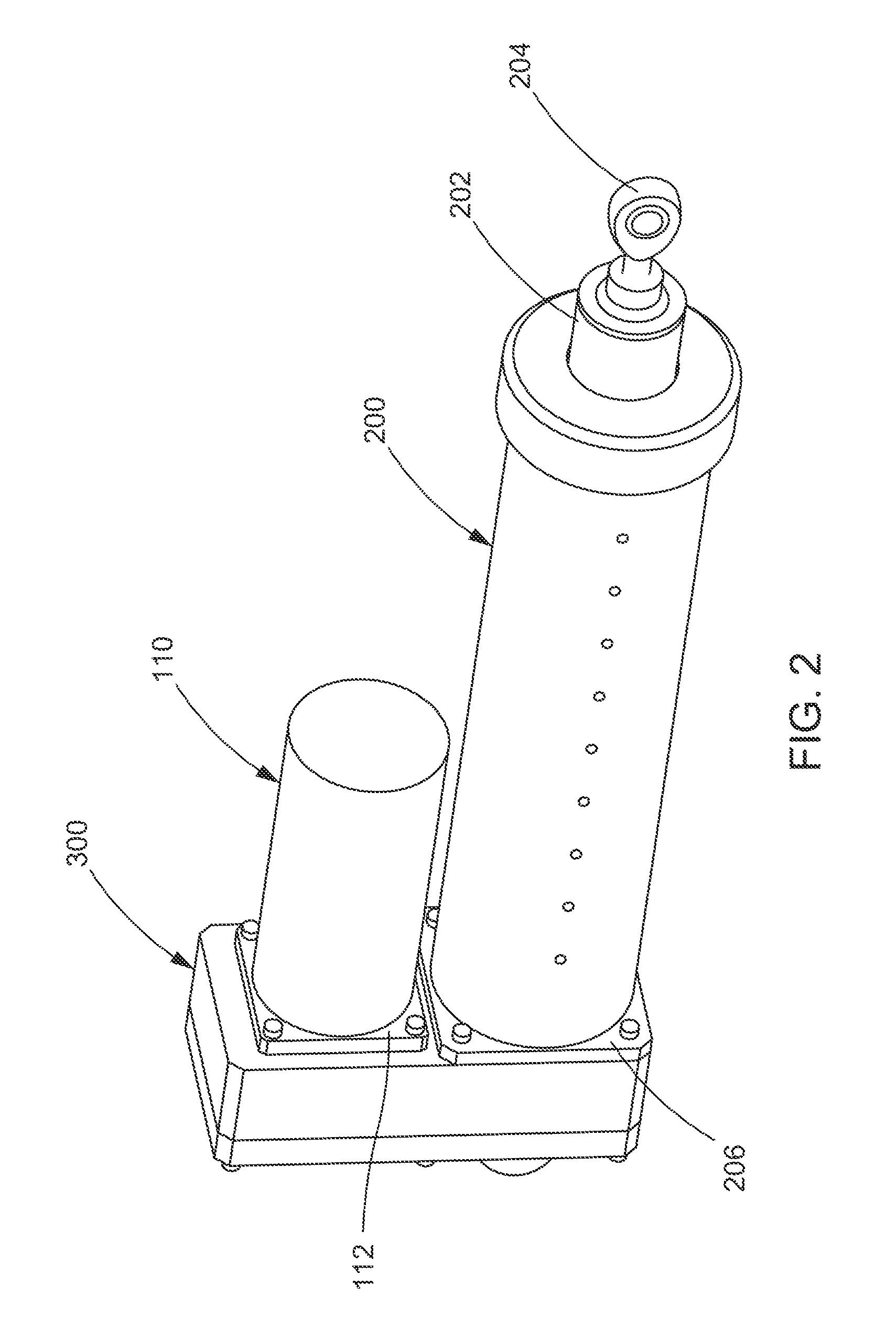
[0032]The invention will now be described with reference to the drawing figures, in which like reference numerals refer to like parts throughout.

[0033]Various aspects of an actuator assembly may be illustrated by describing components that are coupled, attached, and / or joined together. As used herein, the terms “coupled”, “attached”, and / or “joined” are used to indicate either a direct connection between two components or, where appropriate, an indirect connection to one another through intervening or intermediate components. In contrast, when a component is referred to as being “directly coupled”, “directly attached”, and / or “directly joined” to another component, there are no intervening elements present.

[0034]Relative terms such as “lower” or “bottom” and “upper” or “top” may be used herein to describe one element's relationship to another element illustrated in the drawings. It will be understood that relative terms are intended to encompass different orientations of an electric...


PUM


Abstract

An actuator assembly includes an actuation member, a release member, and a source of pressurized gas, wherein during a normal mode of operation, the actuation member and the release member are engaged to move in unison, and wherein during an emergency mode of operation, pressurized gas automatically decouples the actuation member from the release member to move separately. In accordance with yet other aspects of the present disclosure, an electro-mechanical actuator includes an electro-mechanical drive system and an integrated backup system operated by a gas generator, wherein when the backup system is activated, the electro-mechanical drive system is decoupled and the actuator moves to a predetermined position and mechanically locks in place.

Description

CROSS REFERENCE TO PRIOR APPLICATIONS[0001]This application is a continuation of International Application No. PCT / US2013 / 044068, filed Jun. 4, 2013 and designating the U.S., which claims priority to provisional Patent Application No. 61 / 655,331, filed Jun. 4, 2012, both of which are incorporated herein by reference in their entirety.FIELD OF THE INVENTION[0002]The present invention relates to actuator mechanisms, more particularly to an actuator assembly having an integrated emergency backup system.BACKGROUND OF THE INVENTION[0003]Mechanical linear actuators are used for translating rotational motion to linear motion. For example, ball screws are linear actuators that rely on a threaded shaft and a nut housing. The nut housing typically contains ball bearings that engage a helical raceway defined by the threaded shaft. Thus, rotational movement of the shaft translates into linear movement of the nut housing along the shaft. These types of linear actuators are often used in aeronaut...

Claims


Application Information

Patent Timeline
IPC IPC(8): F15B15/14
CPCF15B15/14B64C25/30F16H25/20F16H2025/2081F15B15/088F15B15/19F15B2211/8752F15B2211/8757F16H25/2015F16H2025/2071
Inventor FENN, CHRISTOPHER L.CRONIN, PATRICK
Owner AEROCONTROLEX GROUP
Learn More