
Substrate carrier with integrated electrostatic chuck

a technology of electrostatic chuck and substrate, which is applied in the direction of lighting and heating apparatus, instruments, furniture, etc., can solve the problems of substrate damage, inability to accommodate expansion or repositioning of the mask, and difficulty in controlling the mask portion of the substra

Active Publication Date: 2016-07-07
APPLIED MATERIALS INC
View PDF2 Cites 34 Cited by
  • Summary
  • Abstract
  • Description
  • Claims
  • Application Information

AI Technical Summary

Benefits of technology

The patent describes a substrate carrier with electrodes that generate an electrostatic chucking force to securely hold a substrate during processing. The carrier has a heating / cooling reservoir and a quick disconnect for trapping a heat regulating medium. The invention also includes methods for transferring and processing substrates on the carrier. The technical effects include improved substrate holding capacity, efficient heating and cooling, and control over substrate temperature.

Problems solved by technology

During processing of the substrate in a vertical orientation, it is often difficult to control the mask portion of the substrate.
Expansion or repositioning of the mask cannot be accommodated.
Conventional mechanical clamping carriers used to hold a substrate during transfer and sometimes processing may often result in substrate damage due to the high mechanical clamping force.
This mechanical contact concentrated at the edges of the substrate inevitably creates contact contamination or physical damage, undesirably polluting the substrate.
Particularly, for substrates used for smart phones, plasma display panels, LED or solar cell applications, thin substrates are often utilized, thus increasing the difficulty in transferring the substrates without damage.
In a vertical processing system, temperature control for the substrate carrier during plasma processing has become challenging as poor control of the temperature to the substrate carrier may not only result in material deposition failure, but also affect the chucking ability to the substrate disposed thereon, inevitably leading to inconsistent or undesirable electrical properties of the substrate carrier which adversely affects the carrier's ability to hold substrates.

Method used


Image

  • Substrate carrier with integrated electrostatic chuck
  • Substrate carrier with integrated electrostatic chuck
  • Substrate carrier with integrated electrostatic chuck

Examples


Embodiment Construction

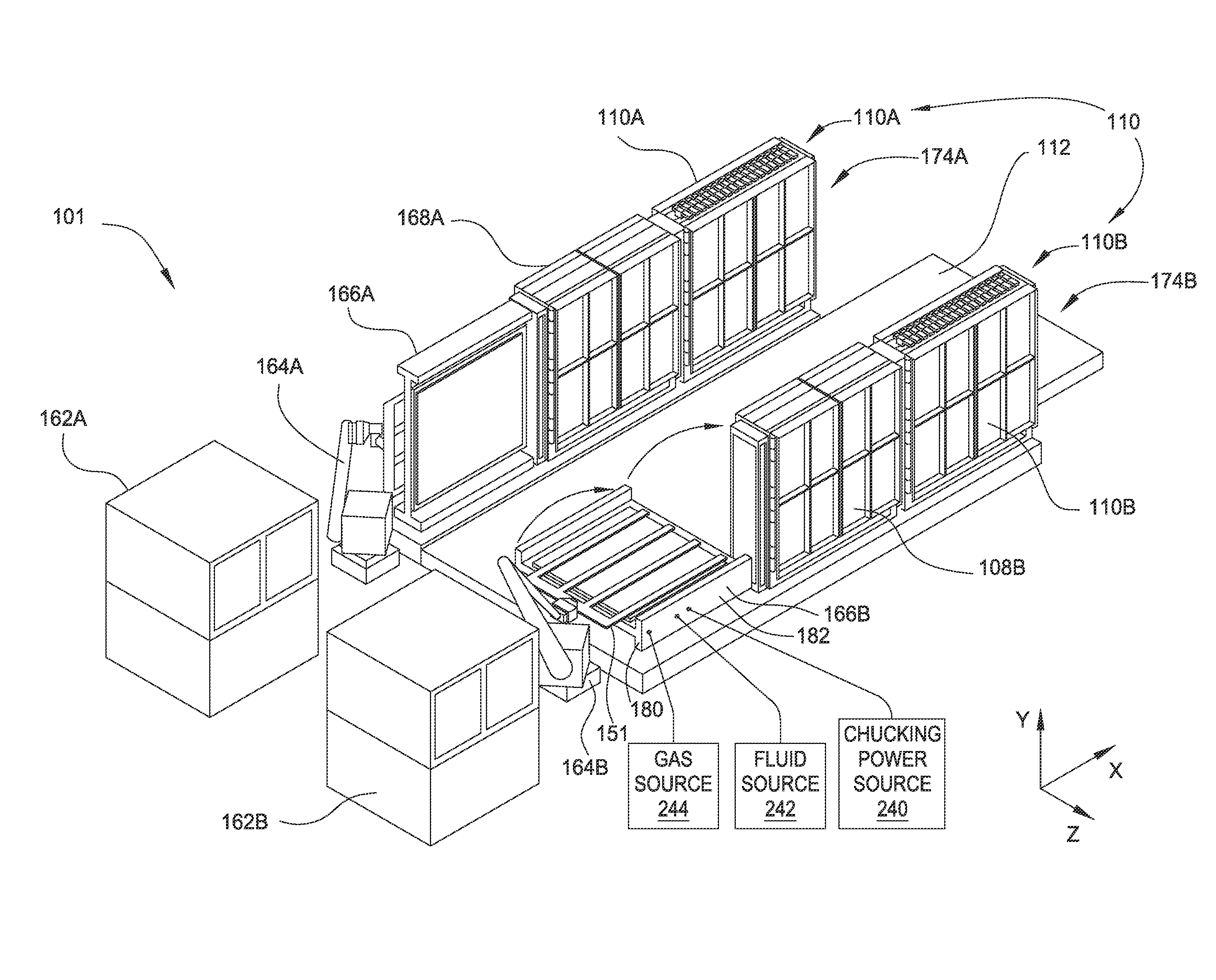
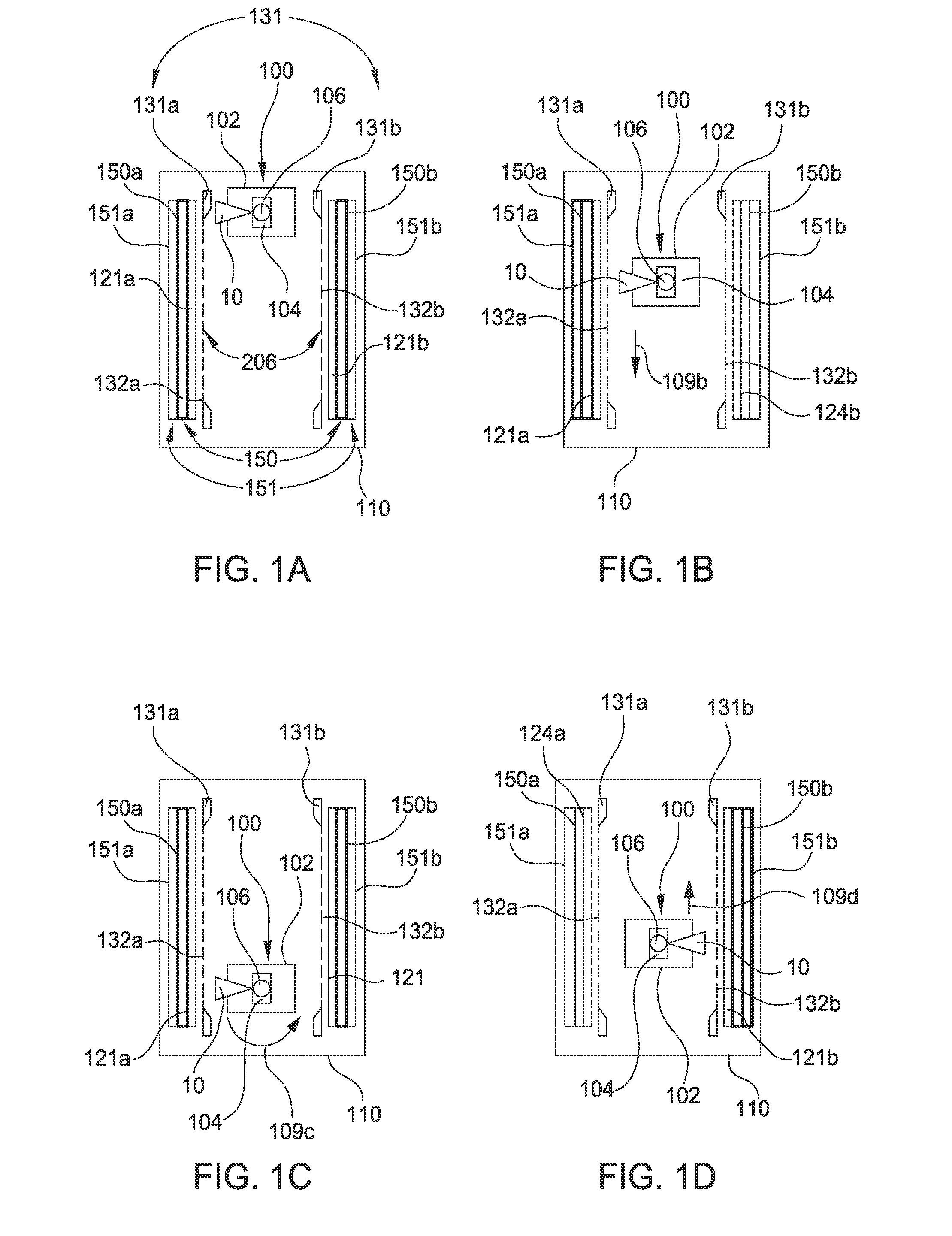
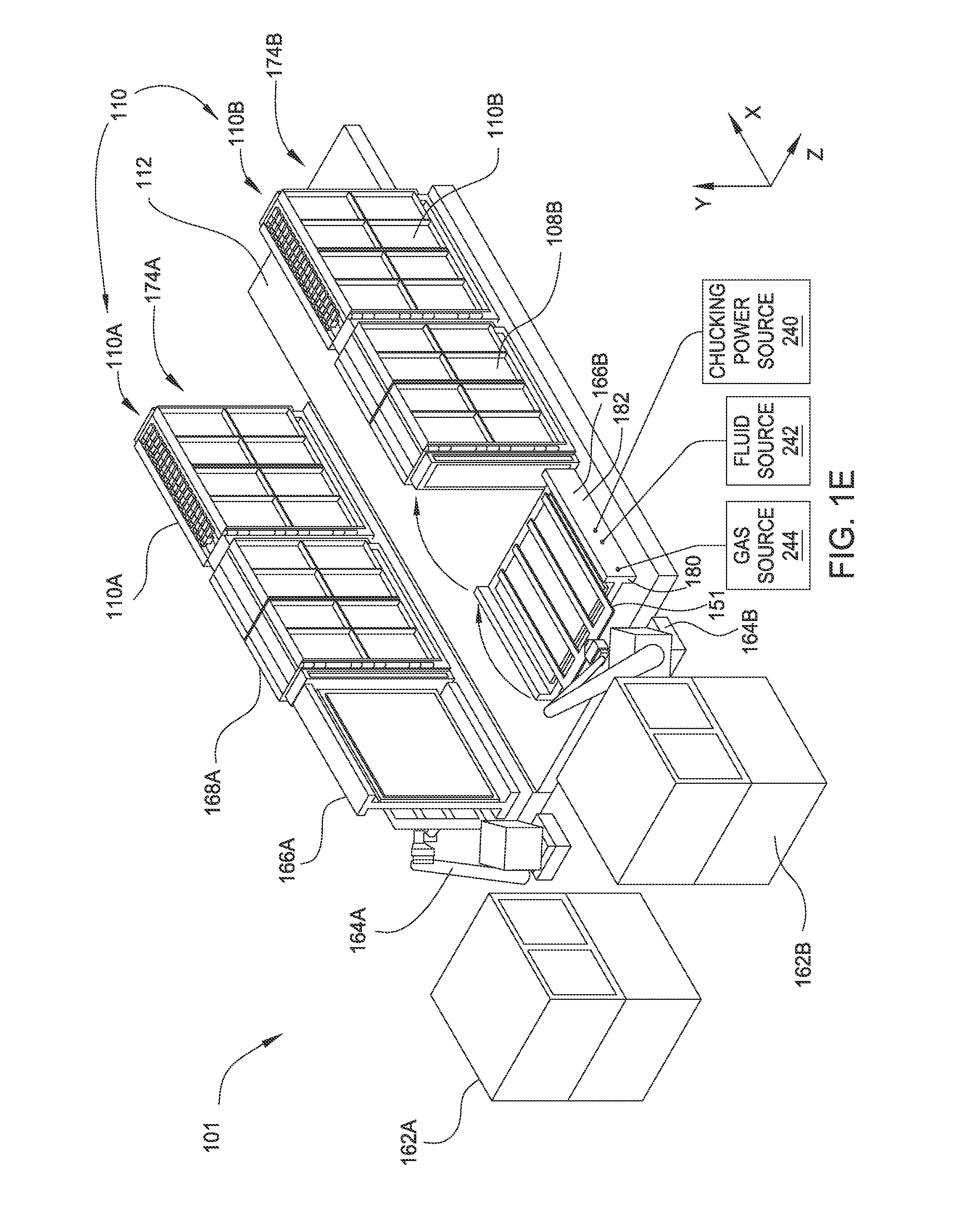
[0033]The present invention generally relates to a substrate carrier suitable for maintaining a substrate in a vertical orientation during processing and methods for using the same. The substrate carrier includes an integrated electrostatic chuck. The substrate carrier may also be temperature controllable so as to control a temperature of the substrate disposed thereon within a desired temperature range.

[0034]The embodiments discussed herein may be practiced utilizing a vertical deposition system, for example a vertical CVD or vertical PVD chamber, such as a modified AKT New Aristo™ Twin PVD system available from Applied Materials, Inc., Santa Clara, Calif. It is to be understood that the embodiments of the invention may be practiced in other processing systems as well, including non-inline (i.e., cluster) systems and including systems sold by other manufacturers. It should also be noted that although the substrate carrier described herein is particularly beneficial for use in verti...


PUM

PropertyMeasurementUnit
Temperatureaaaaaaaaaa
Forceaaaaaaaaaa
Poweraaaaaaaaaa

Abstract

A substrate carrier adapted to use in a processing system includes an electrode assembly and a support base. The electrode assembly is configured to generate an electrostatic chucking force for securing a substrate to the substrate carrier. The support base has a heating / cooling reservoir formed therein. The electrode assembly and the support base form an unitary body configured for transport within a processing system. A quick disconnect is coupled to the body and configured to trap a heat regulating medium in the reservoir heating / cooling reservoir when the body is decoupled from a source of heat regulating medium.

Description

BACKGROUND OF THE INVENTION[0001]1. Field of the Invention[0002]Embodiments of the present invention generally relate to a substrate carrier, and more particularly, a substrate carrier with integrated electrostatic chuck suitable for use in a vertical and other processing systems.[0003]2. Description of the Related Art[0004]Plasma display panels, organic light emitting diodes (OLED) displays and liquid crystal displays are frequently used for flat panel displays. Liquid crystal displays (LCD) generally contain two glass substrates joined together with a layer of a liquid crystal material sandwiched therebetween. The glass substrate may be a semiconductor substrate, or may be a transparent substrate such as a glass, quartz, sapphire, or a clear plastic film. The LCD may also contain light emitting diodes for back lighting.[0005]During manufacturing of flat panel displays or solar panels, plasma processes for depositing material layers on the glass or transparent substrate may be repe...

Claims


Application Information

Patent Timeline
IPC IPC(8): H01L21/683H01L21/67H05B3/03C23C16/458F26B3/00F27B1/08H01L21/673C23C14/50
CPCH01L21/6833H01L21/6732H01L21/67109H05B3/03C23C16/4587F26B3/00F27B1/08C23C14/50H01L21/67718H01L21/67742C23C14/042C23C14/12C23C14/24C23C14/541C23C14/562C23C16/042C23C16/345C23C16/401C23C16/45578C23C16/463C23C16/545B65G49/061B65G49/062B65G49/063G02F1/1303B65G2201/022H10K71/00H01L21/67706H01L21/67712
Inventor WHITE, JOHN M.WANG, ZUOQIAN
Owner APPLIED MATERIALS INC
Learn More