Motor
- Summary
- Abstract
- Description
- Claims
- Application Information
AI Technical Summary
Benefits of technology
Problems solved by technology
Method used
Image

Examples
first embodiment
[0068]A motor according to a first embodiment will now be described.
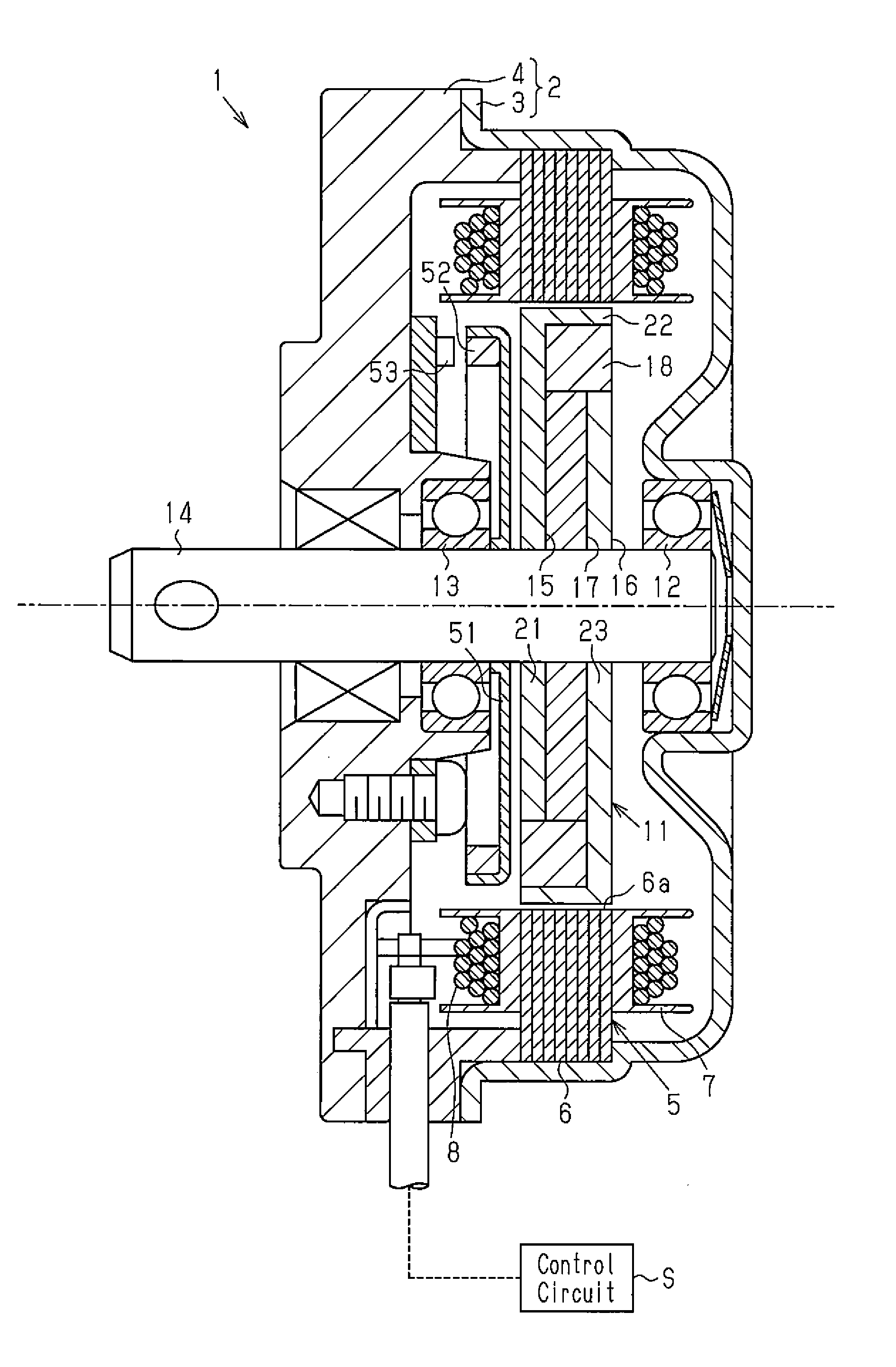
[0069]A motor 1 of the present embodiment illustrated in FIG. 1 is a brushless motor. A motor casing 2, serving as a shell of the motor 1, includes a yoke housing 3, which is cylindrical and has a closed end, and an end plate 4, which closes an opening of the yoke housing 3.
[0070]A stator 5, having an annular shape, is fixed to an inner circumferential surface of the yoke housing 3. The stator 5 includes a stator core 6 a plurality of teeth 6a, which extends inward in a radial direction, and coils 8, which are wound around the teeth 6a with an insulator 7 arranged in between. The stator 5 generates a rotating magnetic field when an external control circuit S supplies driving current to the coil 8.
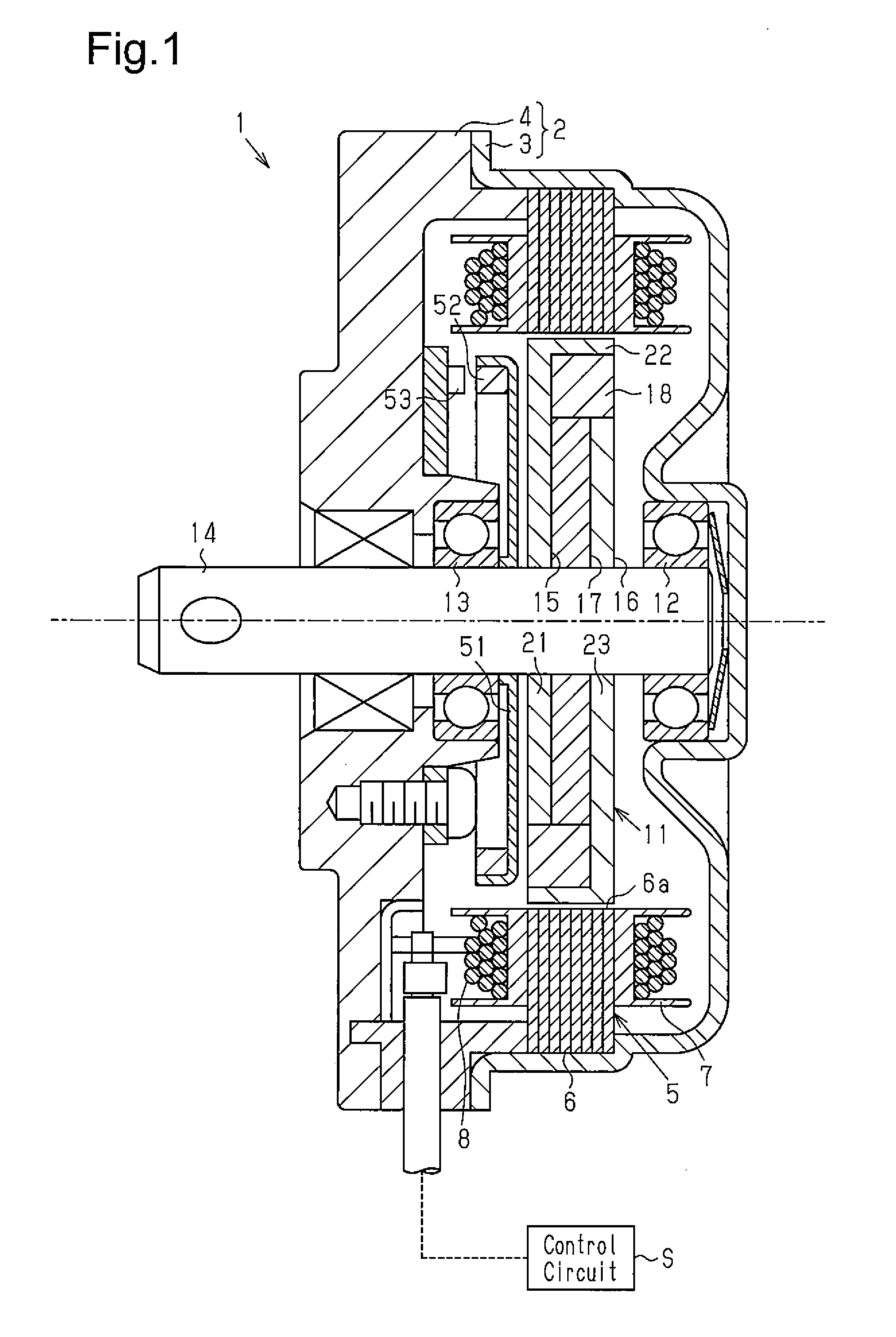
[0071]A rotor 11 is located at an inner side of the stator 5. Two bearings 12 and 13 are respectively arranged on a central portion of the closed end of the yoke housing 3 and a central portion of the end plate 4. The two b...
second embodiment
[0101]A motor according to a second embodiment will now be described. In the second embodiment, same reference numerals are given to those components that are the same as the corresponding components of the first embodiment. Such components will not be described.
[0102]A rotor 61 of the second embodiment, illustrated in FIGS. 8 and 9A, is used instead of the rotor 11 of the first embodiment in the motor 1.
[0103]The rotor 61 includes a cylindrical fixed cylinder 62 fixed to the rotation shaft 14, first and second rotor cores 63 and 64 that are fixed to the fixed cylinder 62, a field magnet 65 located between the first and second rotor cores 63 and 64, and first and second back surface magnets 66 and 67 and first and second interpolar magnets 68 and 69 that are located on an outer circumference of the field magnet 65.
[0104]The first rotor core 63, which is formed by a magnetic steel plate of a soft magnetic material, includes a disk-shaped first core base 71 and a plurality of (four in...
third embodiment
[0146]A motor according to a third embodiment will now be described with reference to FIGS. 14 to 18.
[0147]As illustrated in FIG. 14, a motor casing 212 of a brushless motor 211, serving as the motor, includes a yoke housing 213, which is cylindrical and has a closed end, and an end housing 214, which is a nonmagnetic body formed from an aluminum alloy and closes an opening of the yoke housing 213.
[0148]As illustrated in FIG. 14, a stator 216 is fixed to an inner circumferential surface of the yoke housing 213. The stator 216 includes a stator core 217 and coils 220. The stator core 217 includes a plurality of teeth 217a extending inward in a radial direction. The coils 220 are wound around the teeth 217a with an insulator 219 arranged in between. The stator 216 generates a rotating magnetic field when the external control circuit S supplies driving current to the coils 220.
[0149]As illustrated in FIG. 15, the stator core 217 in the present embodiment includes twelve teeth 217a arra...
PUM
 Abstract
Description
Claims
Application Information
 - R&D
- Intellectual Property
- Life Sciences
- Materials
- Tech Scout
- Unparalleled Data Quality
- Higher Quality Content
- 60% Fewer Hallucinations
Browse by: Latest US Patents, China's latest patents, Technical Efficacy Thesaurus, Application Domain, Technology Topic, Popular Technical Reports.
© 2025 PatSnap. All rights reserved.Legal|Privacy policy|Modern Slavery Act Transparency Statement|Sitemap|About US| Contact US: help@patsnap.com