Heat pipe

a technology of heat pipe and heat flux, which is applied in the direction of indirect heat exchangers, lighting and heating apparatus, etc., can solve the problems of not being able to take into account the cost and effect of heat pipe, the configuration of the heat pipe is still too complex, and the prior art heat pipe cannot meet the demand for discharging a lot of heat and high heat flux, so as to achieve easy manufacturing, improve the quality and yield of heat pipe manufacturing, and improve the effect of heat pipe quality

Inactive Publication Date: 2016-07-14
DELTA ELECTRONICS INC
View PDF7 Cites 7 Cited by
  • Summary
  • Abstract
  • Description
  • Claims
  • Application Information

AI Technical Summary

Benefits of technology

[0009]In view of foregoing subject, an objective of the present invention is to provide a heat pipe with simple structure for increasing heat flux and effectively solving the request of the high-efficient heat dissipation and high heat flux.
[0020]According to above, the heat pipe of the present invention includes a first pipe and a second pipe disposed in the first pipe. Due to simple structure for easy manufacturing, the quality and the yield of the manufacturing of the heat pipe can be increased and the cost can be decreased. Additionally, the heat pipe of the present invention with inner pipe and outer pipe can improve the efficiency of the liquid-gas cycle in the heat pipe and the heat conducting ability of the heat pipe. The heat pipe of the present invention is especially for avoiding the transient heat shock and providing a solution for high-efficient heat dissipation and high heat flux.

Problems solved by technology

The heat pipe of the prior art can not satisfy the demand for dissipating a lot of heat of heat and high heat flux.
However, these improving methods require complicated procedures and lengthy time, and the configuration of the heat pipe is still too complex to be taking into account the costs and effects of the heat pipe.

Method used


Image

  • Heat pipe
  • Heat pipe
  • Heat pipe

Examples


Embodiment Construction

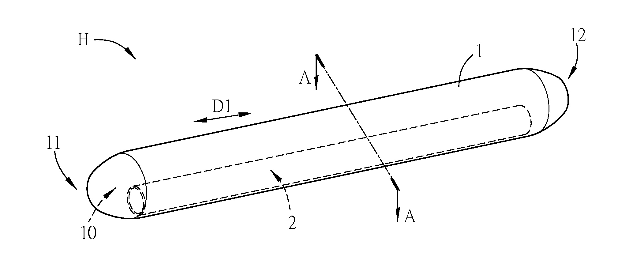
[0033]A heat pipe according to a preferred embodiment of the present invention will be apparent from the following detailed description, which proceeds with reference to the accompanying drawings, wherein the same references relate to the same elements.

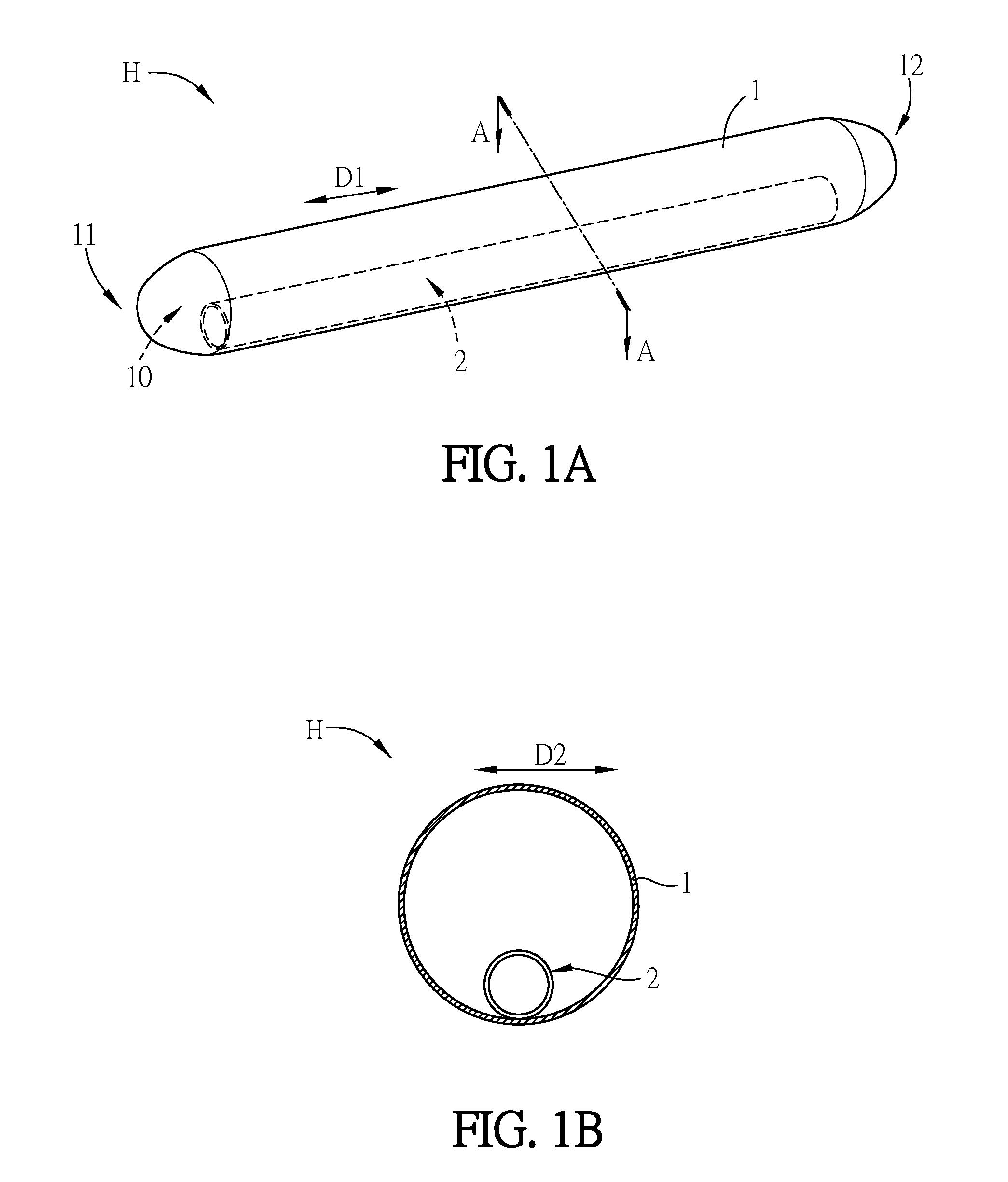
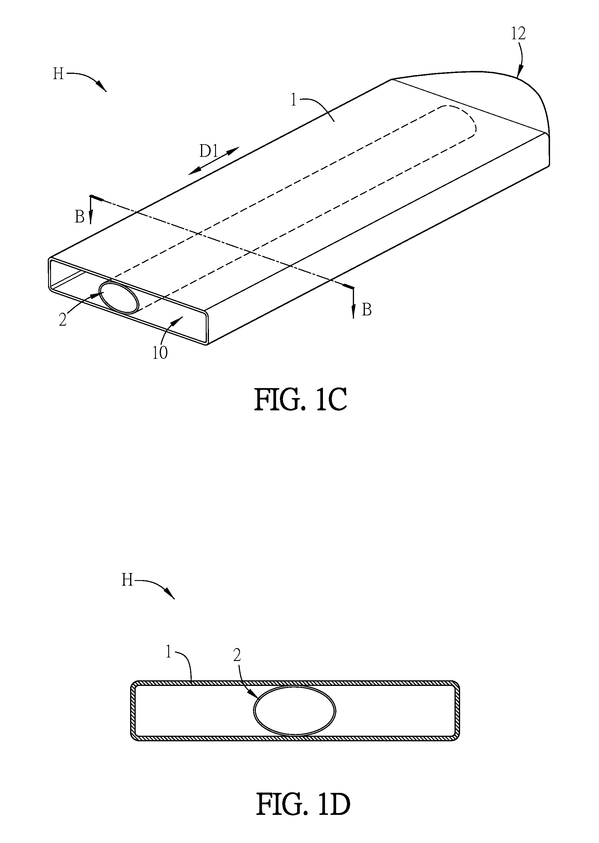
[0034]FIG. 1A is a schematic view of partial heat pipe according to a preferred embodiment of the present invention. FIG. 1B is a cross-sectional view taken along line A-A of the heat pipe in FIG. 1A. In the embodiment, a heat pipe H includes a first pipe 1 and at least one second pipe 2. In the embodiment, one second pipe is 2 is utilized. The first pipe 1 is formed with an enclosed space 10. The second pipe 2 is disposed in the enclosed space 10. There is no wick structure disposed between the first pipe 1 and the second pipe 2.

[0035]In the embodiment, the first pipe 1 is an elliptic cylindrical pipe with a thin wall. A section taken along a radial direction of the first pipe is a uniform section. The first pipe 1 can be made of Cu,...


PUM


Abstract

A heat pipe is disclosed in the present invention. The heat pipe includes a first pipe and at least a second pipe. The first pipe is formed with an enclosed space. The second pipe is disposed in the enclosed space. There is no wick structure disposed between the first pipe and the second pipe.

Description

CROSS REFERENCE TO RELATED APPLICATIONS[0001]This Non-provisional application claims priority to 201510011351.7 filed in People's Republic of China on Jan. 9, 2015, the entire contents of which are hereby incorporated by reference.BACKGROUND OF THE INVENTION[0002]1. Field of Invention[0003]The invention is relative to a heat pipe, especially relative to a heat pipe utilizing vapor pressure difference to drive working fluids.[0004]2. Related Art[0005]A heat pipe of prior art is mainly composed of a closed metal tube, a wick structure and heat transferring fluid filled in the metal tube. An appropriate vacuum degree in the metal tube is maintained for reducing the starting temperature difference of heat pipe. The evaporator of the heat pipe is located at the heat source, and the fluid in the metal tube absorbing the heat generated by the heat source can be evaporated to a vapor. The vapor is flowed to the condenser of the heat pipe according to the difference of the vapor pressure. Th...

Claims


Application Information

Patent Timeline
Patent Type & Authority Applications(United States)
IPC IPC(8): F28D15/02
CPCF28D15/02F28D15/025
Inventor HUANG, SHIH-LINCHEN, CHIU-KUNGWU, SIENWANG, TI-JUN
Owner DELTA ELECTRONICS INC
Why Eureka
Try Eureka