Strain measuring device

a measuring device and a technology of a force sensor, applied in the direction of force measurement by measuring optical property variation, optical radiation measurement, instruments, etc., can solve the problems of mechanical characteristics degraded, cracking, weakening of the structure, etc., to improve the quality and reliability of the measurement

Active Publication Date: 2016-07-14
UNIV DE NANTES
View PDF2 Cites 5 Cited by
  • Summary
  • Abstract
  • Description
  • Claims
  • Application Information

AI Technical Summary

Benefits of technology

[0004]The present invention aims to improve the quality and the reliability of the measurement of the stresses and deformations occurring locally within a volume.

Problems solved by technology

These stresses cause deformations in the volume of these structures that can lead to their mechanical characteristics being degraded.
However, these methods at best make it possible to estimate only a mean value along the axis of the sensor of the components of the stresses or deformations in a fiber placed in the volume under surveillance.
Finally, direct integration of a sensor into the volume under surveillance may lead to weakening of the structure that may be caused by the mechanical quality difference of the materials constituting the sensor or to modification of the distribution of the stresses in the volume of the structure in the vicinity of the sensor.
In the latter case the particular shape of the sensor may lead to local stress concentrations liable to cause the onset of cracking in the vicinity of this sensor.
Moreover, the modification of the stress distribution in the vicinity of the sensor compromises the quality of the measurement, with the risk of it no longer ideally reflecting the magnitudes that it is required to measure [which may lead to using these sensors as threshold warning devices rather than as systems for effecting the tracked measurements].

Method used


Image

  • Strain measuring device
  • Strain measuring device
  • Strain measuring device

Examples


Embodiment Construction

[0054]In the various figures, the same references designate identical or similar elements.

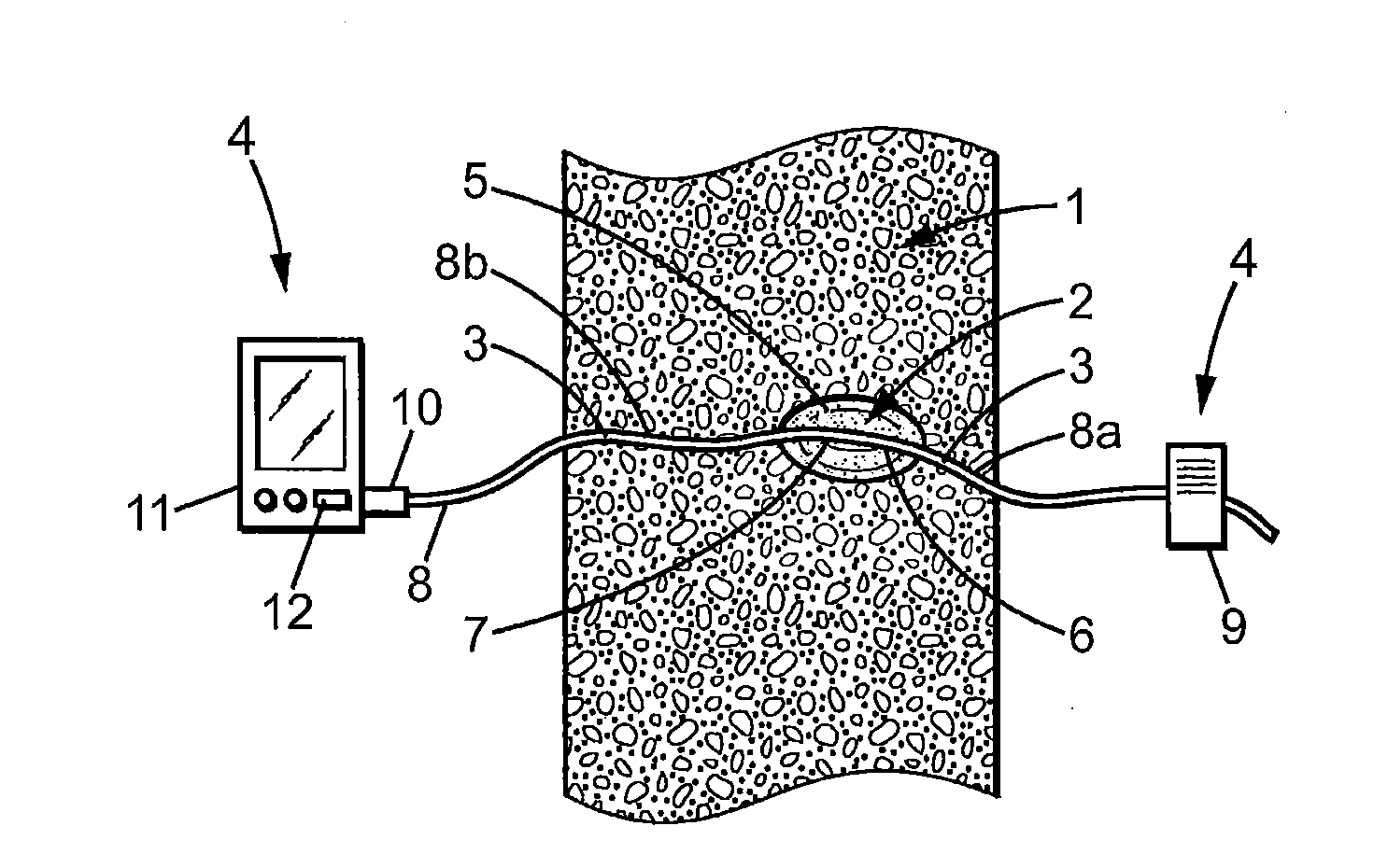
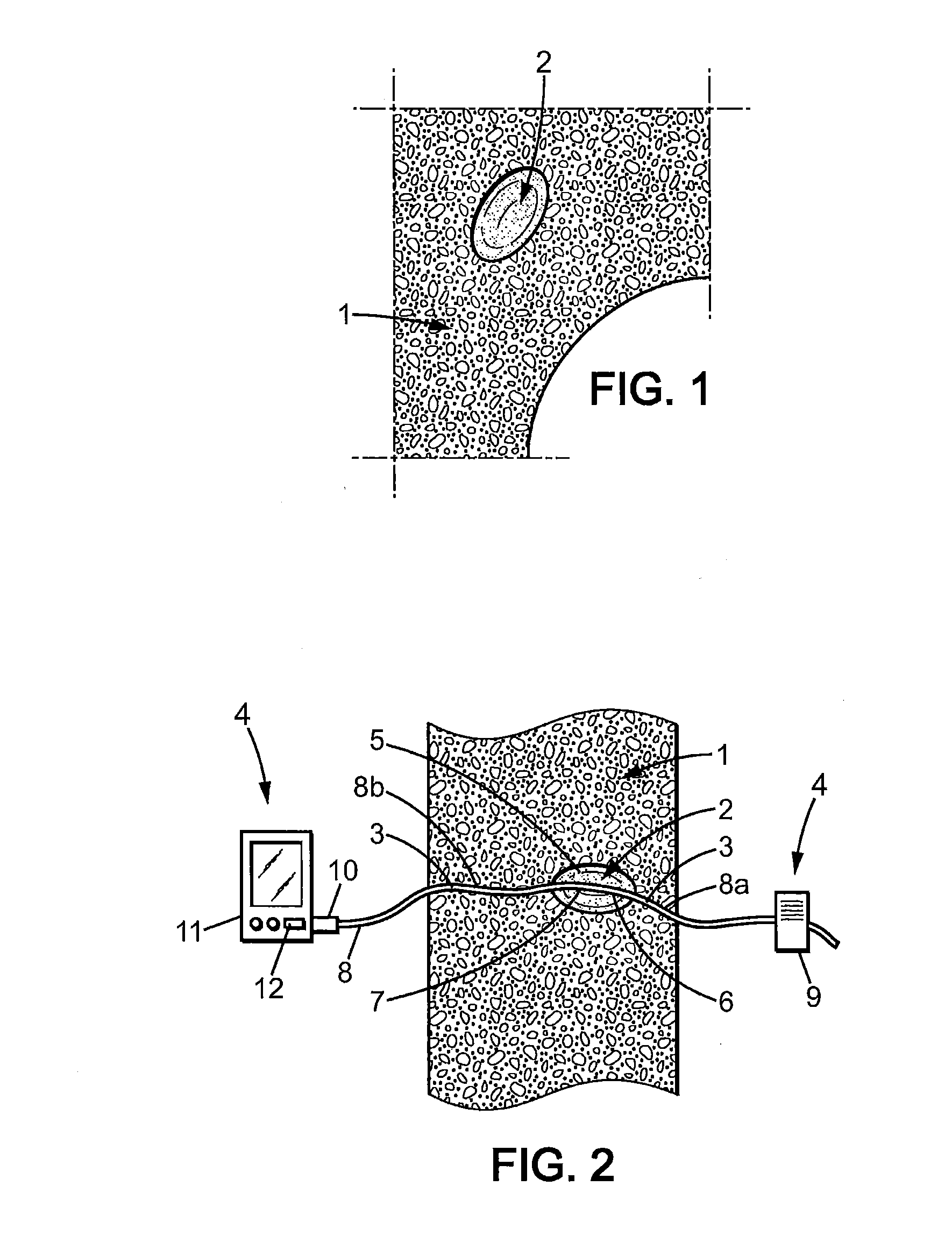
[0055]FIG. 1 represents diagrammatically a part of a structure 1 for which it is required to determine a deformation or a mechanical stress at a localized location 2. The structure 1 is a rigid structure, for example, such as a civil engineering structure, notably constituted of concrete, where appropriate hollowed out and / or reinforced from place to place.

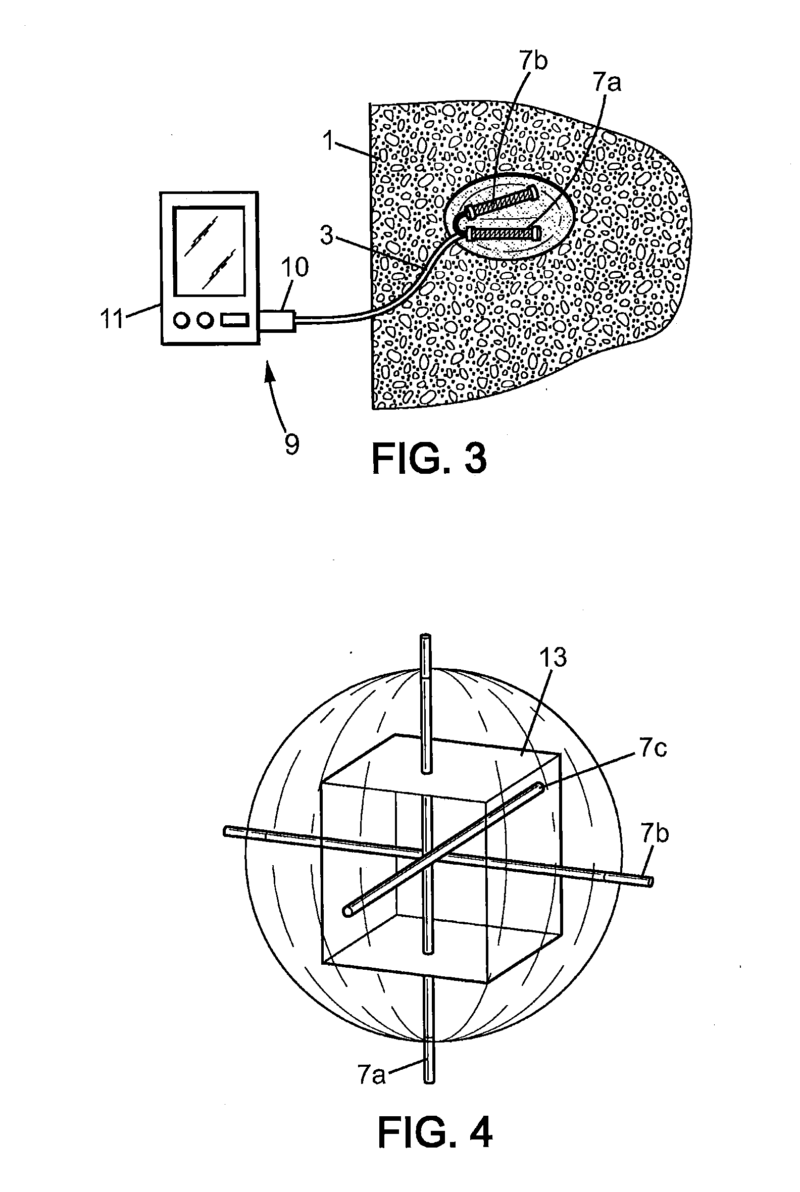
[0056]As can be seen in FIG. 2, the structure includes, at the level of the location 2, a void of specific shape, adapted to receive a test body as described hereinafter. Moreover, at least one channel 3 is provided for connecting the void to an instrumentation area 4.

[0057]The instrumentation area 4 is for example an area external to the structure 1 or a hollow area within the latter or accessible from the outside of the latter, for example. In the FIG. 2 example, there are two instrumentation areas 4 and two channels 3 on respective opposit...


PUM

PropertyMeasurementUnit
mechanical propertiesaaaaaaaaaa
mechanical structureaaaaaaaaaa
volumeaaaaaaaaaa

Abstract

The invention concerns a device for locally measuring strains withth a measurement volume (2) that comprises a test body (5) formed from a homogeneous material of known mechanical properties and ellipsoidal in shape intended to he included in the measurement volume (2), at least one measurement optical fibre (7) for measuring deformation embedded within said test body (5) and means (8) for linking the at least one measurement optical fibre (7) to a system (9, 10, 11) designed to stimulate the at least one measurement optical fibre (7), detect signals coming from the fibres and, by means of an electronic system (11) capable of carrying out calculations, determine strains from at least one of the detected signals and known mechanical properties.

Description

FIELD OF THE INVENTION[0001]The invention concerns a device for measuring stresses or local deformations within a volume that may for example represent a structure or part of a structure.BACKGROUND TO THE INVENTION[0002]The structures that are very routinely used in architecture, in civil engineering structures and generally in fields linked to mechanics must generally suffer mechanical stresses that can evolve over time. These stresses cause deformations in the volume of these structures that can lead to their mechanical characteristics being degraded. To monitor the qualities of these structures it is necessary to be able to measure the evolution of the deformations that are produced in the volume of these structures.[0003]The evolution of the deformations of the structures and the estimation of the stresses that they suffer may be tracked by devices placed on the external surface of the structures such as visual indicators for the deformations or mechanical sensors responsive to ...

Claims


Application Information

Patent Timeline
Patent Type & Authority Applications(United States)
IPC IPC(8): G01L1/24
CPCG01L1/242G01B11/18G01M11/086G01L1/246G01L5/16G01M5/0041G01M5/0091G01B21/32
Inventor FRANCOIS, MARCLECIEUX, YANNLEDUC, DOMINIQUELUPI, CYRIL
Owner UNIV DE NANTES
Why Eureka
Try Eureka