Noise filter

Active Publication Date: 2016-07-14
MITSUBISHI ELECTRIC CORP
View PDF5 Cites 4 Cited by
  • Summary
  • Abstract
  • Description
  • Claims
  • Application Information

AI Technical Summary

Benefits of technology

[0010]In the noise filter according to the invention, the board ground pattern is separated into a plurality of board ground patterns, the separated board ground patterns are connected to a common ground member present outside the board, and the separated board ground patter

Problems solved by technology

However, such a noise filter cannot provide desired noise attenuation character

Method used


Image

  • Noise filter
  • Noise filter
  • Noise filter

Examples


embodiment 1

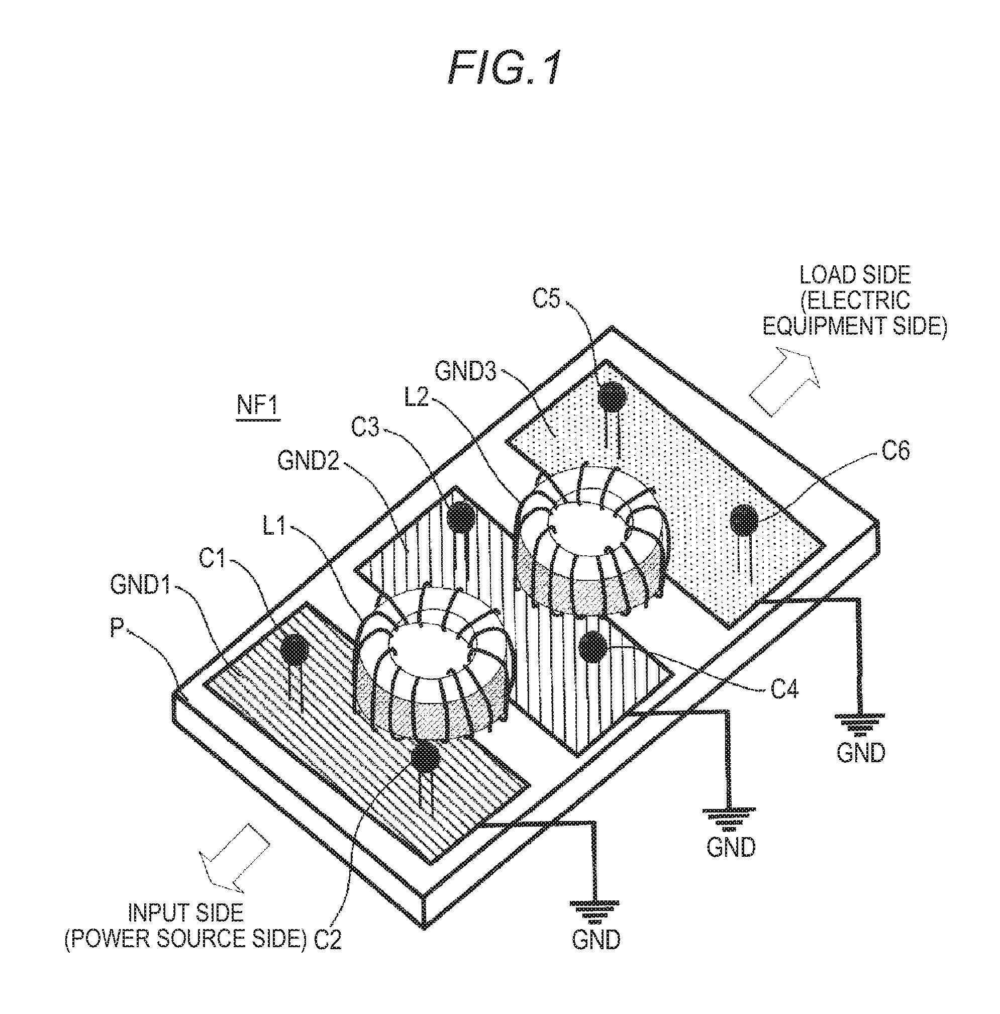
[0030]A noise filter according to embodiment 1 of the present invention will be described below. FIG. 1 is a perspective view schematically illustrating the noise filter according to embodiment 1 of the invention. In FIG. 1, a noise filter NF1 includes a first common mode choke coil L1, which is a coil mounted on the surface of a filter board P as a board, and a second common mode choke coil L2. In addition, the noise filter NF1 includes a first line bypass capacitor C1, a second line bypass capacitor C2, a third line bypass capacitor C3, a fourth line bypass capacitor C4, a fifth line bypass capacitor C5, and a sixth line bypass capacitor C6, which are capacitors mounted on the surface of the filter board P, and a first board ground pattern GND1, a second board ground pattern GND2, and a third board ground pattern GND3, which are board ground patterns. These board ground patterns GND1, GND2, and GND3 are connected to a ground plane G, which is a structure (such as the chassis or th...

embodiment 2

[0052]FIG. 8 is a perspective view schematically illustrating a noise filter according to embodiment 2 of the invention. In FIG. 8, the filter board P is provided with the first and second choke coils L1 and L2, the first to fourth line bypass capacitors C1, C2, C3, and C4, and the first and second board ground patterns GND1 and GND2 as board ground patterns. Here, a filter circuit F1 including the first choke coil L1 and the first and second line bypass capacitors C1 and C2 is referred to as a first filter circuit and a filter circuit F2 including the first choke coil L2 and the third and fourth line bypass capacitors C3 and C4 is referred to as a second filter circuit.

[0053]The first board ground pattern GND1 and second board ground pattern GND2 are separately provided for each of the first filter circuit F1 and the second filter circuit F2 and the first and second board ground patterns GND1 and GND2 are not electrically connected to each other on the filter board P. The first boa...

embodiment 3

[0068]FIG. 14 is a perspective view schematically illustrating a noise filter according to embodiment 3 of the invention. In FIG. 14, on the filter board P, the first and second common mode choke coils L1 and L2, the first to fourth line bypass capacitors C1, C2, C3, and C4, the first and second board ground patterns GND4 and GND5, and the third and fourth board ground patterns GND6 and GND7 are provided. The first common mode choke coil L1 is disposed over the first and second board ground patterns GND4 and GND5 and the second common mode choke coil L2 is disposed over the third and fourth board ground patterns GND6 and GND7.

[0069]The first to fourth board ground patterns GND4, GND5, GND6, and GND7 are separated from each other and are not electrically connected to each other on the filter board P. The first board ground pattern GND4 is connected to the ground plane G by the first connection member SC1 such as a screw, the second board ground pattern GND5 is connected to the ground...


PUM


Abstract

A noise filter inserted between the power source side and the load side of a main circuit for which noise is reduced to attenuate noise of the main circuit using a filter circuit including the coil and the capacitor. In the noise filter, the board ground pattern is separated into a plurality of board ground patterns, the separated board ground patterns are connected to a common ground member present outside the board, the separated board ground patterns are formed as solid patterns, and adjacent board ground patterns of the separated board ground patterns are disposed so as to have a spacing equal to or less than a predetermined distance.

Description

TECHNICAL FIELD[0001]The present invention relates to a noise filter to be inserted into an AC power line or a DC line having undergone input current smoothing of electric equipment such as an AC-DC converter or inverter.BACKGROUND ART[0002]In various types of electric equipment products and electronic equipment products, conducted noise generated from a power line, communication line, or the like connected to electric equipment or electronic equipment needs to be restricted by EMC (Electromagnetic Compatibility) regulations or the like. Accordingly, a noise filter is connected between the commercial power line and various types of electronic equipment. However, such a noise filter cannot provide desired noise attenuation characteristics, so a technique for effectively suppressing noise needs to be developed.[0003]For example, the technique disclosed in PTL 1 is known as a technique for improving the noise attenuation characteristics of such a noise filter. The technique disclosed i...

Claims


Application Information

Patent Timeline
IPC IPC(8): H03H7/01H03H1/00
CPCH03H7/0115H03H2001/0085H03H1/00H02M1/126H03H1/0007H03H7/09H03H7/427H03H2001/0035
Inventor KAWAMURA, MAO
Owner MITSUBISHI ELECTRIC CORP
Why Eureka
Try Eureka