Object Space Calibration of Plenoptic Imaging Systems

a plenoptic imaging and object space technology, applied in the field of plenoptic imaging system calibration, can solve the problems of different plenoptic imaging system architecture, different calibration and processing procedures, and and achieve the effect of improving the processing of plenoptic images

Inactive Publication Date: 2016-07-14
RICOH KK
View PDF2 Cites 36 Cited by
  • Summary
  • Abstract
  • Description
  • Claims
  • Application Information

AI Technical Summary

Benefits of technology

[0009]Various embodiments overcome the limitations of the prior art by calibrating a plenoptic imaging system by controlling the propagation directions of light in object space. An object is adjustable to deliver collimated light propagating along different propagation directions, and possibly also from different lateral locations in the object plane if desired. The plenoptic imaging system under calibration captures plenoptic images of the object adjusted to different propagation directions. The captured plenoptic images include superpixels, each of which includes subpixels. Each subpixel captures light from a corresponding light field viewing direction. Based on the captured plenoptic images, a calibration module calculates which propagation directions map to which subpixels. The mapping defines the light field viewing directions for the subpixels. This can be used to improve processing of plenoptic images captured by the plenoptic imaging system.

Problems solved by technology

However, the architecture of a plenoptic imaging system is different from that of a conventional imaging system, and therefore requires different calibration and processing procedures.
Several challenges are found in the processing of plenoptic images.
First, the alignment of the microlens array is never perfect and the effect of rotation of the microlens array is quite observable.
This rotation introduces a large amount of difficulties for image reconstruction because the data points do not fall onto a regular sampling grid.
Manual determination of parameters, such as center of lenslet, pixels under each lenslet, spacing of lenslets, etc., is difficult and time consuming.
A drawback of current techniques is that they neglect possible aberrations in the exit pupil images collected by the sensor.
These aberrations can cause an incorrect calibration to be produced.

Method used


Image

  • Object Space Calibration of Plenoptic Imaging Systems
  • Object Space Calibration of Plenoptic Imaging Systems
  • Object Space Calibration of Plenoptic Imaging Systems

Examples


Embodiment Construction

[0026]The figures and the following description relate to preferred embodiments by way of illustration only. It should be noted that from the following discussion, alternative embodiments of the structures and methods disclosed herein will be readily recognized as viable alternatives that may be employed without departing from the principles of what is claimed.

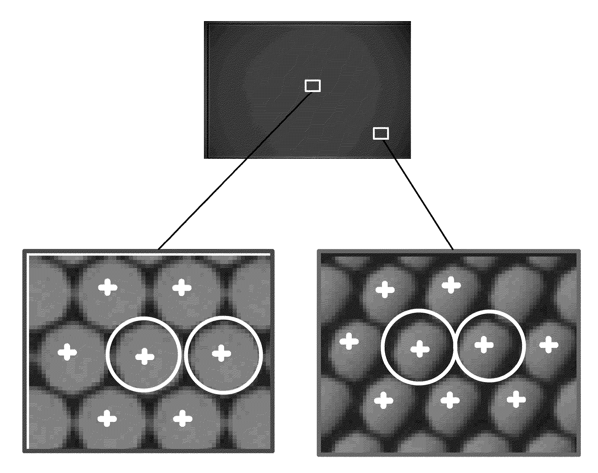
[0027]Various embodiments overcome the limitations of the prior art by calibrating a plenoptic imaging system by controlling the propagation directions of light in object space. An object is adjustable to deliver collimated light propagating along different propagation directions, and possibly also from different lateral locations in the object plane if desired.

[0028]One implementation uses collimated light reflected from a mirror in the object plane. The light beam is wide enough to fill the aperture of the primary lens. The propagation direction of the light beam can be controlled by tilting the mirror. By collecting plenopt...


PUM


Abstract

A collimated object is adjustable to produce collimated light propagating along different propagation directions. The plenoptic imaging system under calibration captures plenoptic images of the object adjusted to different propagation directions. The captured plenoptic images includes superpixels, each of which includes subpixels. Each subpixel captures light from a corresponding light field viewing direction. Based on the captured plenoptic images, a calibration module calculates which propagation directions map to which subpixels. The mapping defines the light field viewing directions for the subpixels. This can be used to improve processing of plenoptic images captured by the plenoptic imaging system.

Description

BACKGROUND[0001]1. Field of the Invention[0002]This technology relates generally to calibrating plenoptic imaging systems.[0003]2. Description of the Related Art[0004]The plenoptic imaging system has recently received increased attention. It can be used to recalculate a different focus point or point of view of an object, based on digital processing of the captured plenoptic image. The plenoptic imaging system also finds application in multi-modal imaging, using a multi-modal filter array in the pupil plane of the primary imaging module. Each filter is imaged at the sensor, effectively producing a multiplexed image of the object for each imaging modality of the filter array. Other applications for plenoptic imaging systems include varying depth of field imaging and high dynamic range imaging.[0005]However, the architecture of a plenoptic imaging system is different from that of a conventional imaging system, and therefore requires different calibration and processing procedures. Sev...

Claims


Application Information

Patent Timeline
Patent Type & Authority Applications(United States)
IPC IPC(8): H04N17/00G06T7/00
CPCH04N17/002G06T2207/10052G06T7/0018G01J3/0208H04N23/55G06T7/80
Inventor MENG, LINGFEILU, LIYANGBEDARD, NOAHBERKNER, KATHRIN
Owner RICOH KK
Why Eureka
Try Eureka