Expedient Processing and Waveform Inversion of Seismic Data

a technology of seismic data and waveform inversion, which is applied in the field of seismic data expedient processing and waveform inversion, can solve the problems of not contributing to any production, not being able to accurately predict the effects of hydraulic fracturing, and being subject to an increase in confining stress in the rock, etc., and achieves rapid generation and processing of waveform data.

Active Publication Date: 2016-07-21
JYOTI BEHURA
View PDF3 Cites 19 Cited by
  • Summary
  • Abstract
  • Description
  • Claims
  • Application Information

AI Technical Summary

Benefits of technology

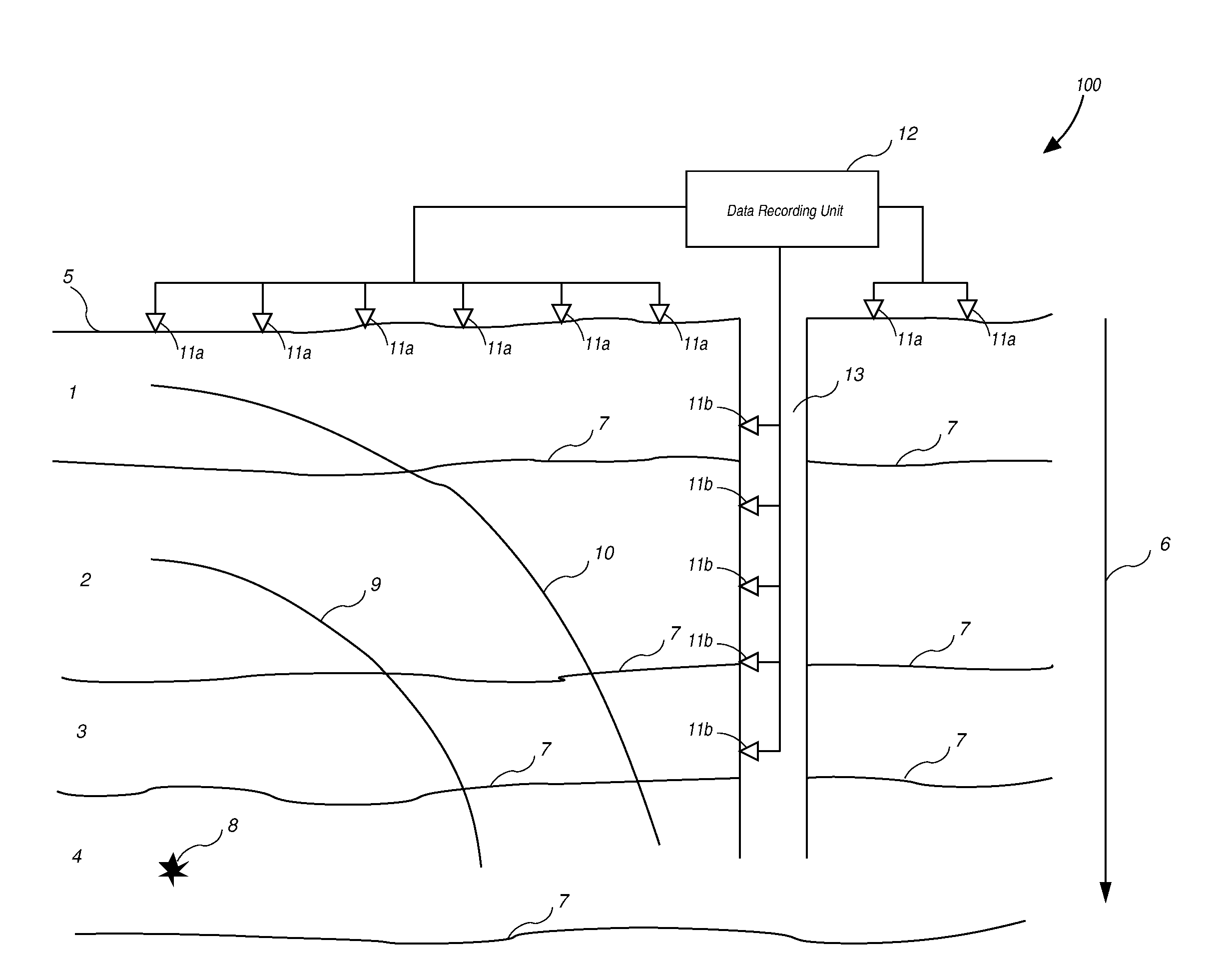
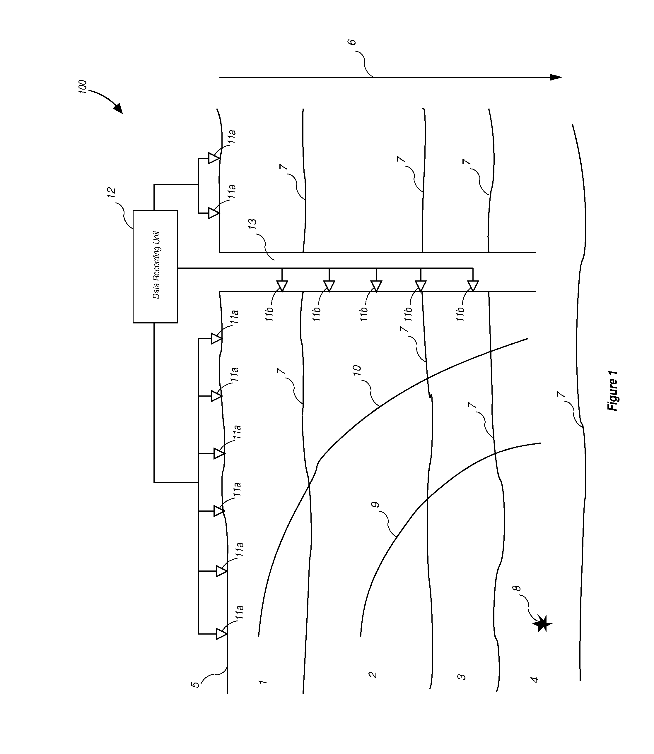
[0014]The present method for expediently processing seismic data for subsurface mapping with waveform inversion has been devised to provide rapid generation and processing of waveform data generated in the field at an arrangement of surface and

Problems solved by technology

Yet at other locations, where the formation has neither been fractured nor has experienced a pore-pressure increase because of the lack of hydraulic communication with the well bore, the rocks might be subjected to an increase in confining stress.
The third zone with confining-stress effects only, however, will not contribute to any production because of the lack of hydraulic communication with the well.
There are two major drawbacks of this approach.
First, the imaged hypocenters yield an incomplete picture of the effects of hydraulic fracturing.
Not all rock property changes from fracturing result in seismic activity and many of the changes that do result in seismic activity might be below the noise threshold.
Second, the imaged hypocenters are most likely inaccurate.
These velocities will be quite different from the velocities resulting from hydraulic fracturing and therefore inappropriate for imaging.
Moreover, traveltime tomography of microseismic events needs arrival time picking, through manual or automatic means, which might incorporate errors into imaging.
Microseismic data, however, can span over several minutes, ho

Method used


Image

  • Expedient Processing and Waveform Inversion of Seismic Data
  • Expedient Processing and Waveform Inversion of Seismic Data
  • Expedient Processing and Waveform Inversion of Seismic Data

Examples


example

[0058]FIG. 4 through FIG. 12 present a synthetic example of reducing the volume of microseismic data and inverting the resulting waveforms for obtaining said velocity combination V and source amplitude distribution using the method described in this invention.

[0059]FIG. 4 is the true compressional-wave velocity model VP that is used to generate the compressional-wave data. FIG. 5 is the true shear-wave velocity model VS that is used to generate the shear-wave data. The spatial extent of the model is 3.5 km in the x-direction and 2.37 km in the z-direction.

[0060]FIG. 6 shows the true compressional- and shear-wave velocity model combination V=VPVS / (VP−VS) of the velocity models in FIG. 4 and FIG. 5 that the reduced waveforms are sensitive to.

[0061]FIG. 7 shows the spatial locations of 80 sources used in generating the compressional- and shear wave data. The amplitudes of all the sources are the same and equal to unity. Receivers are located on all four boundaries of the model at an in...


PUM


Abstract

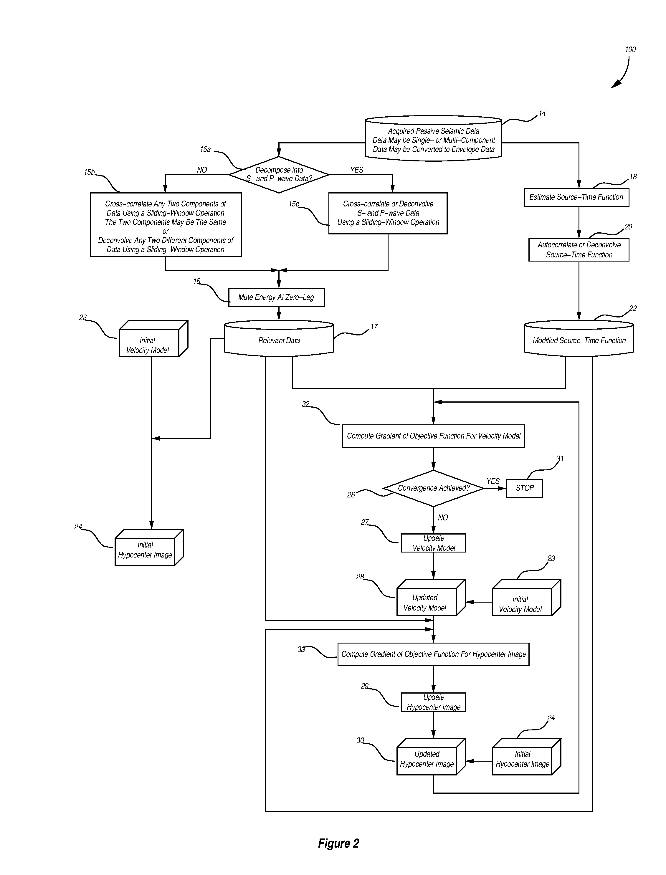
A method for expediently processing and inverting elastic wave data to reduce the amount of data and to determine a physical properties model of the material medium and a source properties model. The data are processed to generate waveforms containing the phase difference between compressional- and shear-wave arrivals using auto-correlation, cross-correlation, or deconvolution of said data sensed at each of an arrangement of sensors, whereby said lengthy elastic wave data records are reduced substantially in time. Said waveform data are thereafter inverted using waveform inversion by modifying the source term in the equation of motion, wherein the source term is mathematically expressed as a product of time-independent source properties volume defined at every location in space within said material medium and a space-independent source-time function, whereby no prior knowledge of the number of sources, spatial distribution of source location, source amplitude, or source focal mechanism is needed.

Description

CROSS-REFERENCE TO RELATED APPLICATIONS[0001]This application claims the benefit of U.S. Provisional Application No. 62 / 104,063, filed 15 Jan. 2015, and U.S. Provisional Application No. 62 / 205,842, filed 17 Aug. 2015, by the present inventor, which are incorporated by reference.FEDERALLY SPONSORED RESEARCH OR DEVELOPMENT[0002]Not applicableSEQUENCE LISTING OR PROGRAM[0003]Not applicableCOPYRIGHT NOTICE[0004]Some portions of the disclosure of this patent document may contain material subject to copyright protection. The copyright owner has no objection to the facsimile reproduction by anyone of the patent document or ensuing disclosure as it appears on record at the Patent and Trademark Office, but otherwise reserves all copyright rights whatsoever.BACKGROUND OF THE INVENTION[0005]The present invention relates to a method for expediently processing elastic wave data through reduction of said data and use it for subsurface mapping with waveform inversion. More particularly, the presen...

Claims


Application Information

Patent Timeline
IPC IPC(8): G01V1/36G01V1/30
CPCG01V1/305G01V1/366
Inventor BEHURA, JYOTI
Owner JYOTI BEHURA
Why Eureka
Try Eureka