Rotor for brushless motor
- Summary
- Abstract
- Description
- Claims
- Application Information
AI Technical Summary
Benefits of technology
Problems solved by technology
Method used
Image

Examples
first embodiment
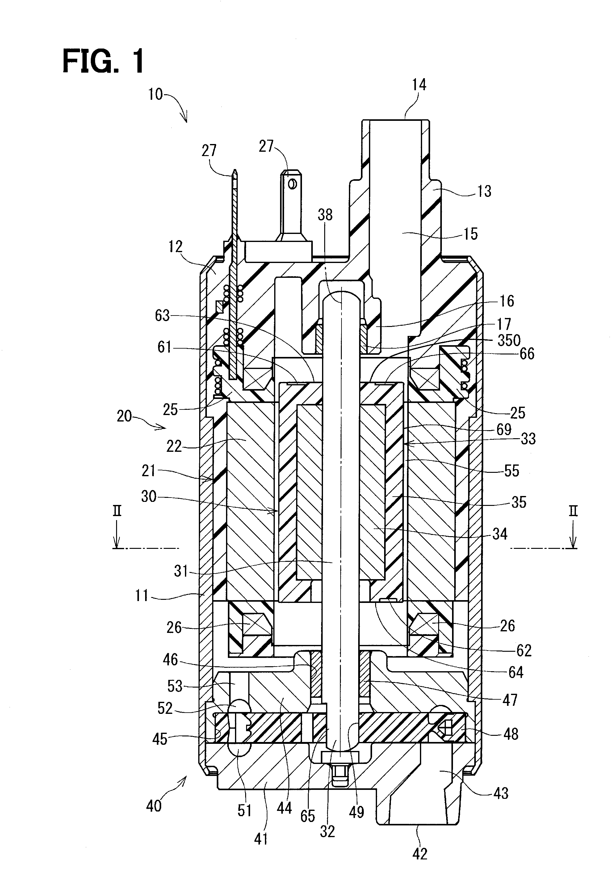
[0025]A rotor of a first embodiment of the present disclosure is applied to a fuel pump 10 shown in FIG. 1. The fuel pump 10 is an in-tank pump that is installed in a fuel tank (not shown). The fuel pump 10 draws fuel from the fuel tank through a suction port 42 shown at a lower side in FIG. 1 and discharges the drawn fuel to an internal combustion engine through a discharge port 14 shown at an upper side in FIG. 1.
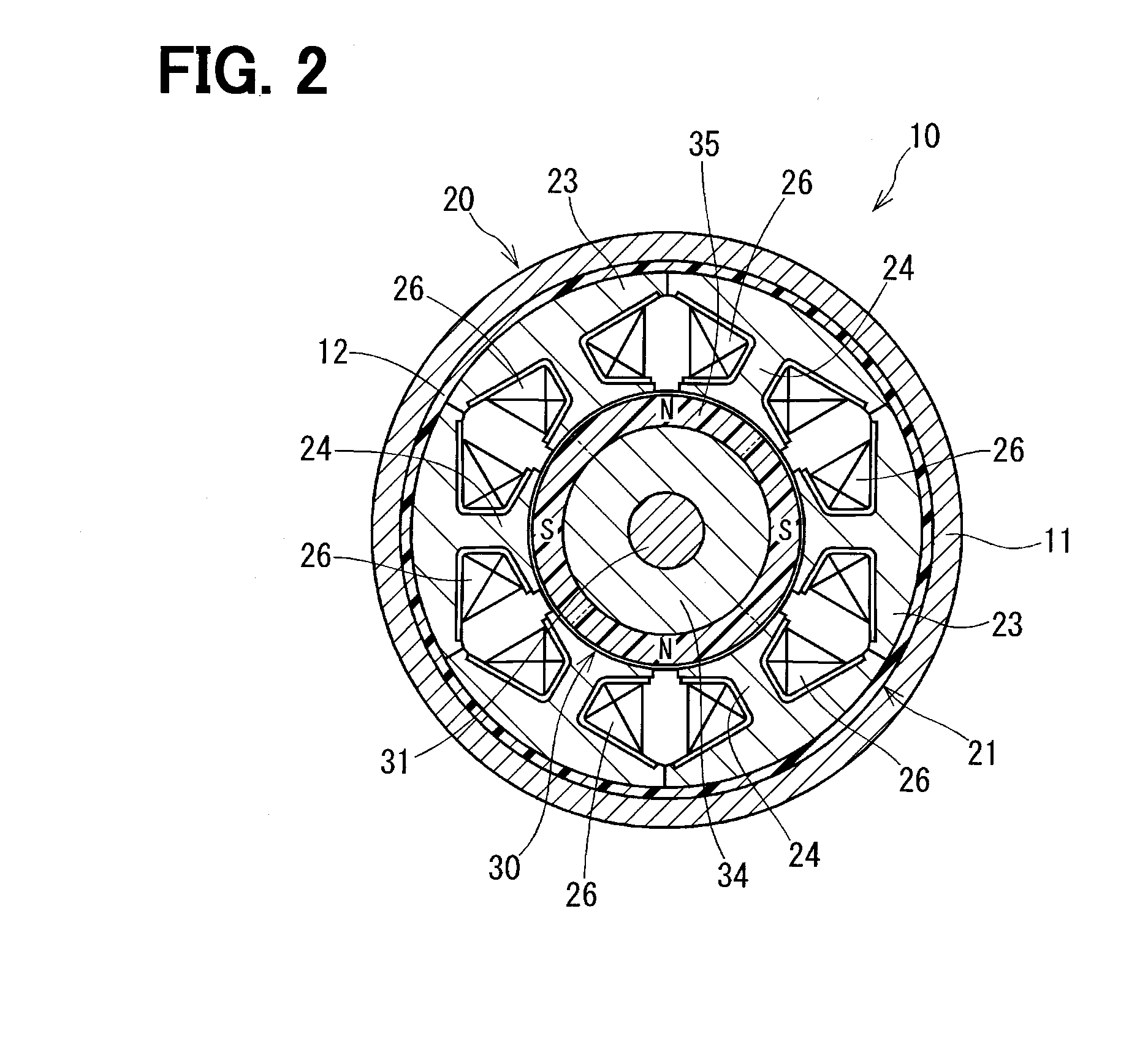
[0026]First of all, an entire structure of the fuel pump 10 will be described with reference to FIGS. 1 and 2.
[0027]The fuel pump 10 includes a motor arrangement 20 and a pump arrangement 40. An outer shell of the fuel pump 10 includes a housing 11, a pump cover 41 and a cover end 12. In the following description of the fuel pump 10, the upper side of FIG. 1 will be referred to as a discharge port 14 side, and the lower side of FIG. 1 will be referred to as a suction port 42 side.
Outer Shell
[0028]The housing 11 is configured into a cylindrical tubular form.
[0029]The pump ...
second embodiment
[0065]A characteristic structure of a rotor 80 according to a second embodiment of the present disclosure will be described with reference to FIGS. 12 and 13.
Bonded Magnet
[0066]A permanent magnet 82 of a rotor core 81 of the rotor 80 is a bonded magnet that is formed through molding of a mixture material that is a mixture of thermoplastic resin, such as PPS (polyphenylene sulfide), and magnetic powder. In the present embodiment, a neodymium bonded magnet is used as the bonded magnet.
Balance Correcting Portion
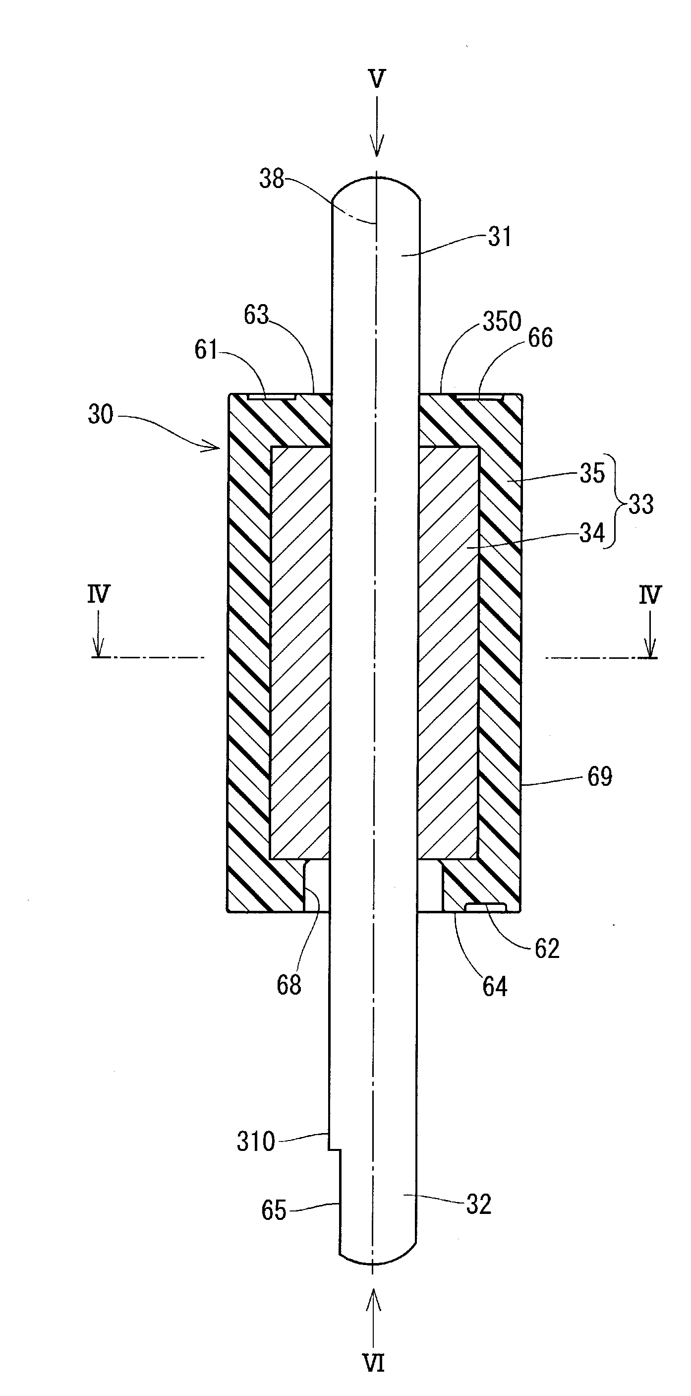
[0067]The permanent magnet 82 includes projections 83, 84 in an outer wall 820. The projections 83, 84 serve as balance correcting portions (balance correcting means) for correcting a dynamic balance of the rotor 80. Similar to the first embodiment, the first end surface 63, the second end surface 64 and the outer peripheral surface 69 are seamlessly and integrally formed in the outer wall 820. The first projection 83 is formed in the first end surface 63 of the outer wall 820, ...
third embodiment
[0072]A rotor 90 according to a third embodiment of the present disclosure will be described with reference to FIG. 14.
[0073]A permanent magnet 92 of a rotor core 91 of the rotor 90 is formed by coating a sintered magnetic body 93 with a protective film 94 made of resin (a resin material). The protective film 94 is formed as follows. That is, an integrated body, in which the sintered magnetic body 93 is installed to the radially outer side of the inner core 34, is placed in a mold, and the resin in a hot molten state is injected into the mold. The protective film 94 forms an outer wall 920 of the permanent magnet 92.
[0074]The protective film 94 has a first recess 95 and a second recess 96, which are formed at the time of molding the protective film 94. The first recess 95 and the second recess 96 are similar to the first recess 61 and the second recess 62 of the first embodiment. Specifically, the first end surface 63, the second end surface 64 and the outer peripheral surface 69 ar...
PUM
 Abstract
Description
Claims
Application Information
PatSnap Eureka turns technology decisions into work you can execute. Powered by our Innovation Knowledge Graph, it runs expert workflows across engineering, life sciences, materials and intellectual property. Get your review-ready output in minutes.


