Amplifying stage working point determination

a technology of working point and amplifier, applied in the field of amplifier circuit, can solve the problems of poor service coverage and bitrate, large amount of distortion and/or non-linearity to the signal, and high distortion at the outpu

Active Publication Date: 2016-07-21
BIRD TECH GROUP
View PDF8 Cites 8 Cited by
  • Summary
  • Abstract
  • Description
  • Claims
  • Application Information

AI Technical Summary

Problems solved by technology

Distributed systems have been developed for providing coverage and high bitrates in locations for which the traditional radio base station concept results in poor service coverage and bitrates.
Class B amplifiers are power efficient but add a relatively large amount of distortion and/or non-linearity to the signal.
Class C amplifiers conduct less than half of the input signal and the distortion at the output is high.
However, high power efficiencies are possible.
Usage of power amplification in communication systems for amplification of the RF signals, which is necessary in order to provide sufficient coverage and bitrates, has a problem in lack of linearity of the power amplifiers.
Non-linearity of the power amplifiers prevents the power amplifiers to accurately reproduce the signal being applied to its input port.
Also, non-linear power amplifiers used in a transmitter in

Method used


Image

  • Amplifying stage working point determination
  • Amplifying stage working point determination
  • Amplifying stage working point determination

Examples


Embodiment Construction

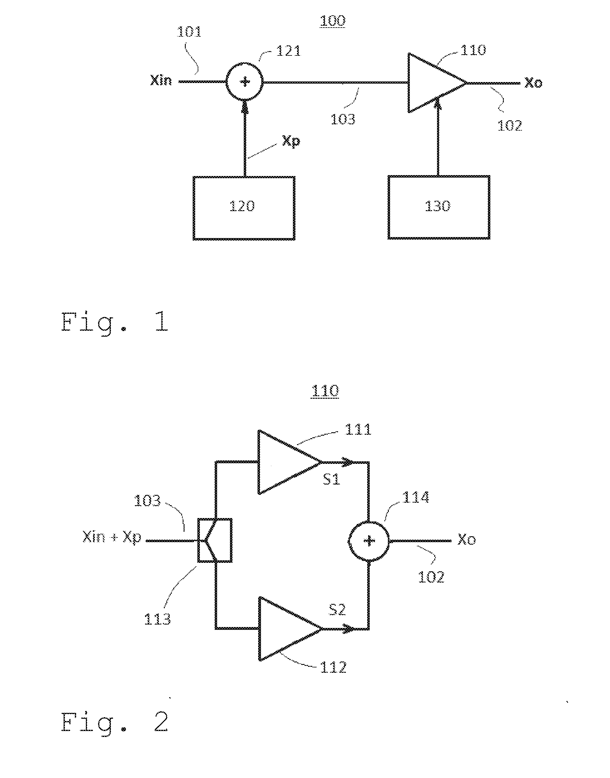
[0038]FIG. 1 schematically shows an amplifier circuit 100 according to the present invention. The amplifier circuit 100 amplifies an input signal Xin being applied on an input 101 of the amplifier circuit 100. The amplifier circuit 100 includes an amplifying stage 110 and a predistortion stage 120. The predistortion stage 120 is arranged for providing a predistortion signal Xp, which is added to the input signal Xin in a combiner 121. By adding the predistortion signal Xp to the input signal Xin, a compensation for non-linearities later being added by the amplifying stage 110 is provided. Thus, the signal being outputted at the combiner output 103 is a combined input and predistortion signal Xin+Xp. The combined input and predistortion signal Xin+Xp is then amplified in the amplifying stage 110. The amplifier circuit 100 further includes an output 102, on which the amplified predistorted output signal X0 is outputted;

[0039]According to the present invention, the working point unit 1...


PUM


Abstract

An amplifier circuit including an amplifying stage and a predistortion stage is disclosed. The amplifier circuit outputs an output signal Xo. The predistortion stage is arranged for providing a predistortion signal Xp to be added to an input signal Xin of the amplifier circuit in order to compensate for non-linearites of said amplifying stage. According to the present invention, the amplifier circuit includes a working point unit arranged for determining a suitable working point WPsuitable to be used for said amplifying stage based on said predistortion signal Xp, and for adjusting an actual working point WPactual being used by said amplifying stage towards said suitable working point WPsuitable.

Description

FIELD OF THE INVENTION[0001]The present invention relates to an amplifier circuit as defined in the preamble of claim 1.[0002]The present invention also relates to a method for an amplifier circuit as defined in the preamble of claim 24.[0003]The present invention also relates to a computer program and to a computer program product.RELATED ART AND BACKGROUND OF THE INVENTION[0004]There is a very large, and still rapidly growing, demand for wireless communication services today. Mobile telephone services are used to a very large extent, e.g. for telephone conversations and text messages. Also, high speed wireless communication is used for a large number of applications, such as internet browsing, streaming of music, films and / or television, and the like.[0005]Since the demand for wireless communication services is very high, and the end users expect the wireless services to be available essentially everywhere they go, the wireless communication system coverage must cover very large g...

Claims


Application Information

Patent Timeline
IPC IPC(8): H03F1/32H03F3/193H03F3/21H03F1/02
CPCH03F1/3282H03F1/0288H03F3/193H03F2200/451H03F2201/3233H03F2203/21131H03F3/211H03F1/3247H03F3/189
Inventor KEREK, DANIELLIDBERG, PETER
Owner BIRD TECH GROUP
Why Eureka
Try Eureka