
Shaping a curved rotor blade

a rotor blade and curved technology, applied in the direction of wind motors, wind motors with parallel air flow, wind turbines, etc., can solve the problems of increasing the need for rotor blade space, reducing the possibility of fixing the shaping tool, and reducing the danger of oscillation

Inactive Publication Date: 2016-07-28
SIEMENS GAMESA RENEWABLE ENERGY AS
View PDF7 Cites 0 Cited by
  • Summary
  • Abstract
  • Description
  • Claims
  • Application Information

AI Technical Summary

Benefits of technology

The patent text describes a new way to shape curved rotor blades for storage and transportation. This new method is easier to use, safer, and takes up less space, making it more convenient for storage and transport.

Problems solved by technology

Whilst pre-bending rotor blade has a great advantage during operation of the wind turbine, transport and storage of such pre-bent rotor blades is getting increasingly complicated: the stronger the bend, the more space is needed for the rotor blade during storage and / or transport.
This constitutes severe problems, in particular during transport—for instance such vehicles cannot pass under bridges any more.
Similarly, if the pre-bend mainly extends sidewards, narrow sections on streets or curvatures cannot be passed by such vehicle any more.
Such fixed positioning may be released after the storage and / or transport so that the shaping tool can again be extracted from the interior of the rotor blade—which is preferred because in wind turbine operation the pretension caused by the shaping tool is often undesired.

Method used


Image

  • Shaping a curved rotor blade
  • Shaping a curved rotor blade
  • Shaping a curved rotor blade

Examples


first embodiment

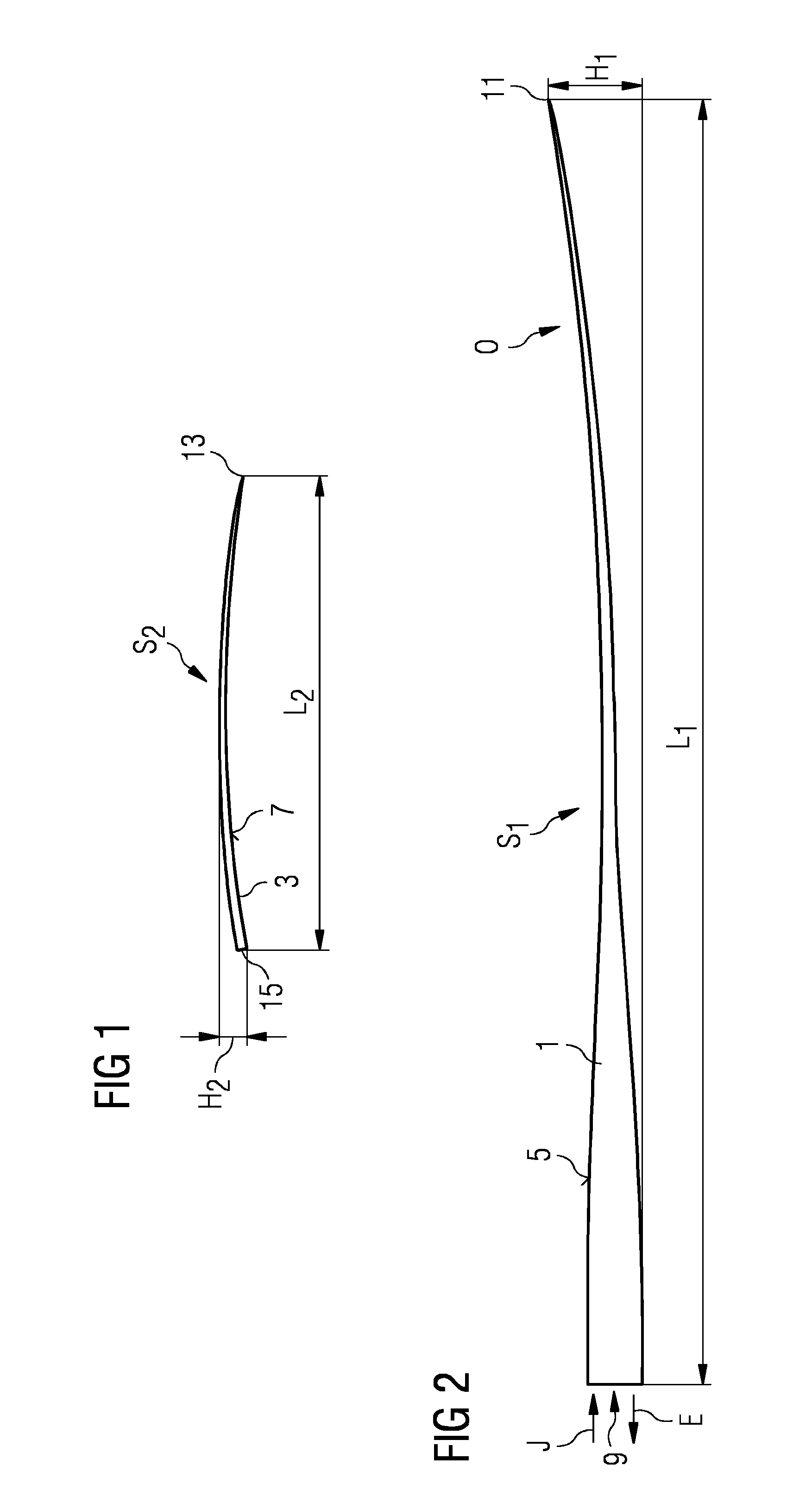
[0042]FIG. 1 shows a side view of a shaping tool 3 according to the invention with an outer surface 7 and with a bent shape S2. The shaping tool 3 comprises a first (root) end 15 and a second (tip) end 13. The principal length, i.e. principal longitudinal extension L2 of the shaping tool 3 extends from the first end 15 to the second end 13. Along that longitudinal extension L2 the shape S2 of the rotor blade is bent such that both the first end 15 and the second end 13 are positioned lower than a middle region of the shaping tool 3. Therefore, the shaping tool 3 due to its shape S2 has an overall larger principal height H2 than the height of any of its cross-sections.

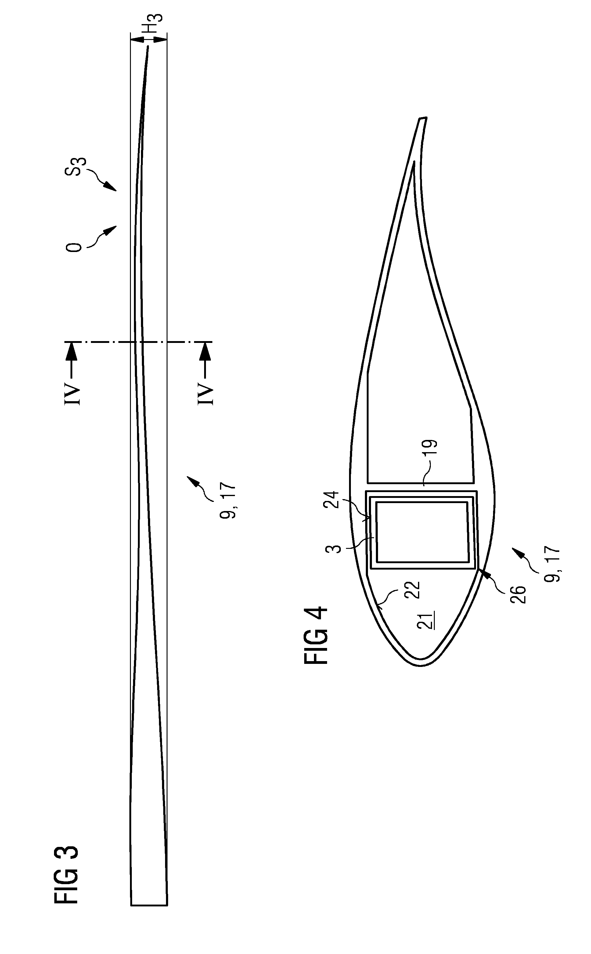
[0043]FIG. 2 shows a corresponding pre-bent rotor blade 1 with an outer surface 5 and a pre-bent shape S1. The rotor blade 1 extends along its principal longitudinal extension L1 from a root end 9 to a tip 11. The principal longitudinal extension L1 is a projection of the rotor blade 1 from root 9 to tip 11 onto a plane...

third embodiment

[0049]FIG. 6 depicts a shaping tool 3″ which can be used in the context of embodiments of the invention. The shaping tool 3″ comprises a first part 3a″ and a second part 3b″ which parts 3a″, 3b″ are interconnected at a connection interface 25. The second part 3b″ can be moved to and fro along a principal direction G into and out of the first part 3a″. This is achieved by means of an actuator 23 which can be for instance realized as an electric motor and / or as a hydraulic and / or pneumatic actuator which is connected to both parts 3a″, 3b″ in such way that it moved the two parts 3a″, 3b″ relative to each other, i.e. by introducing a part of the second part 3b″ into the inner of the (essentially hollow) first part 3a″ or by introducing a part of the first part 3a″ into the inner of the (essentially hollow) second part 3b″. This way the distance between the root end 15″ of the first part 3a″ and the tip end 13′ of the second part 3b″ can be varied—the shaping tool 3″ is again extendable...


PUM


Abstract

A method is provided of shaping a curved rotor blade for storage and / or transport such that an overall cross-extension of the rotor blade is reduced in at least one direction perpendicular to a longitudinal principal extension of the rotor blade. The method includes the step of introducing a shaping tool into an interior of the rotor blade, which shaping tool is preferably stiffer than the rotor blade at least in a direction defined by the cross-extension in the at least one direction. A shaping tool is also provided.

Description

CROSS-REFERENCE TO RELATED APPLICATIONS[0001]This application claims priority to PCT Application No. PCT / EP2014 / 068122, having a filing date of Aug. 27, 2014, based off of EP Application No. 13187530.4 having a filing date of Oct. 7, 2013, the entire contents of which are hereby incorporated by reference.FIELD OF TECHNOLOGY[0002]The following concerns a method of shaping a curved rotor blade, in particular a rotor blade of a wind turbine, for storage and / or transport such that an overall cross-extension of the rotor blade is reduced in at least one direction perpendicular to a longitudinal principal (i.e. overall) extension of the rotor blade. The following also concerns a shaping tool for that purpose and the use of such shaping tool.BACKGROUND[0003]Horizontal axis wind turbines with a rotor on their upwind side have become (apart from a few exceptions) the standard in the wind turbine industry. Thereby, a nacelle is aligned essentially horizontally on top of a wind turbine tower. ...

Claims


Application Information

Patent Timeline
Patent Type & Authority Applications(United States)
IPC IPC(8): F03D1/00F03D1/06
CPCF03D1/0675F03D1/005F05B2260/02F03D13/40Y02E10/72
Inventor ENEVOLDSEN, PEDER BAY
Owner SIEMENS GAMESA RENEWABLE ENERGY AS
Learn More