Power cable gas barrier

a technology of power cable and gas barrier, which is applied in the direction of power cables, cables, insulating conductors/cables, etc., can solve the problems of equipment damage, equipment exposed to high-temperature and/or high-pressure environments,

Inactive Publication Date: 2016-07-28
SCHLUMBERGER TECH CORP
View PDF5 Cites 23 Cited by
  • Summary
  • Abstract
  • Description
  • Claims
  • Application Information

AI Technical Summary

Problems solved by technology

Equipment used in the oil and gas industry may be exposed to high-temperature and/or...

Method used


Image

  • Power cable gas barrier
  • Power cable gas barrier
  • Power cable gas barrier

Examples


Embodiment Construction

[0023]The following description includes the best mode presently contemplated for practicing the described implementations. This description is not to be taken in a limiting sense, but rather is made merely for the purpose of describing the general principles of the implementations. The scope of the described implementations should be ascertained with reference to the issued claims.

[0024]A gas well may be defined by its gas oil ratio (GOR). For example, some states have statutes that provide definitions, for example, where a gas well is one where the GOR is greater than 100,000 ft3 / bbl or 100 Mcf / bbl.

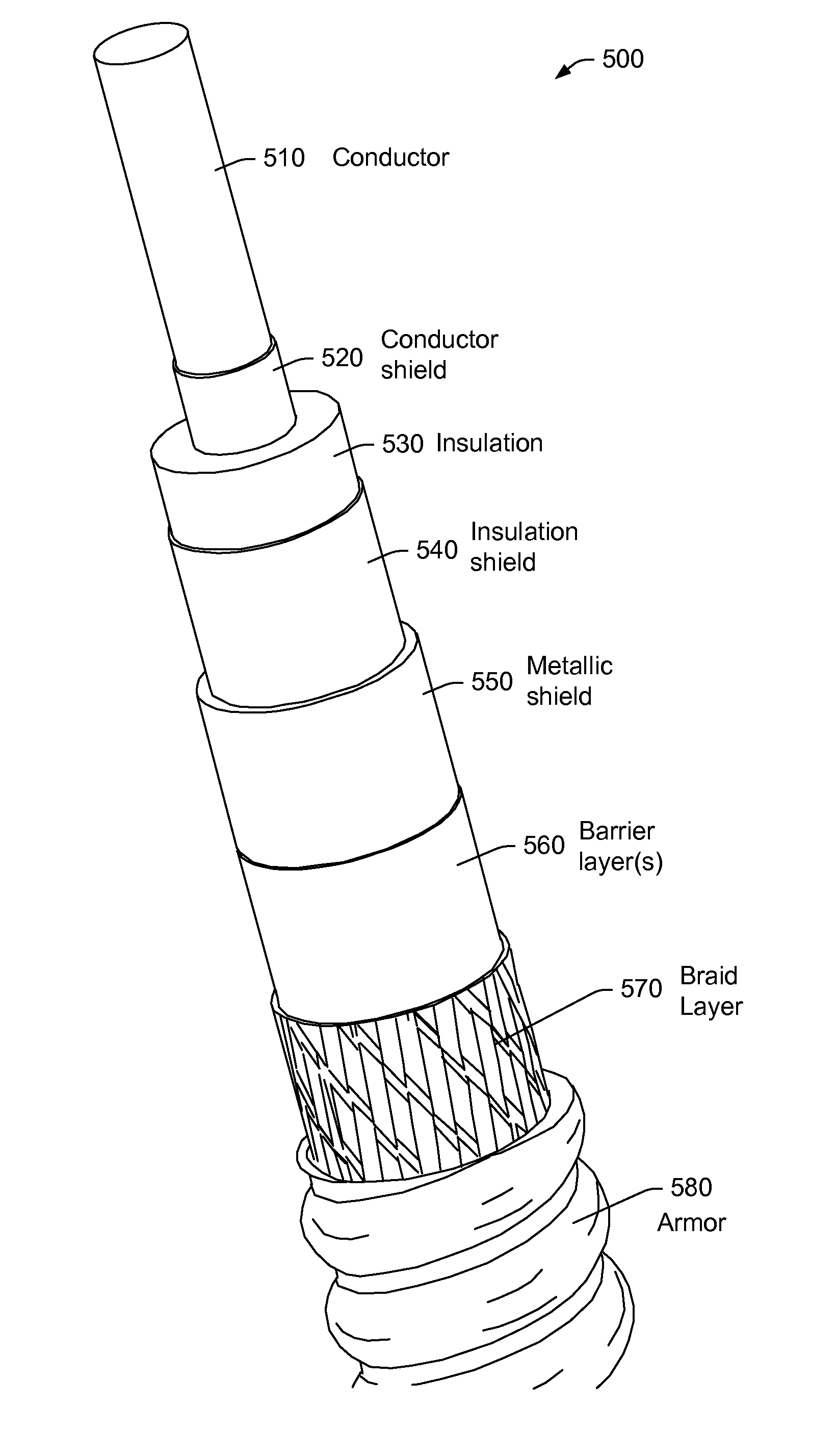
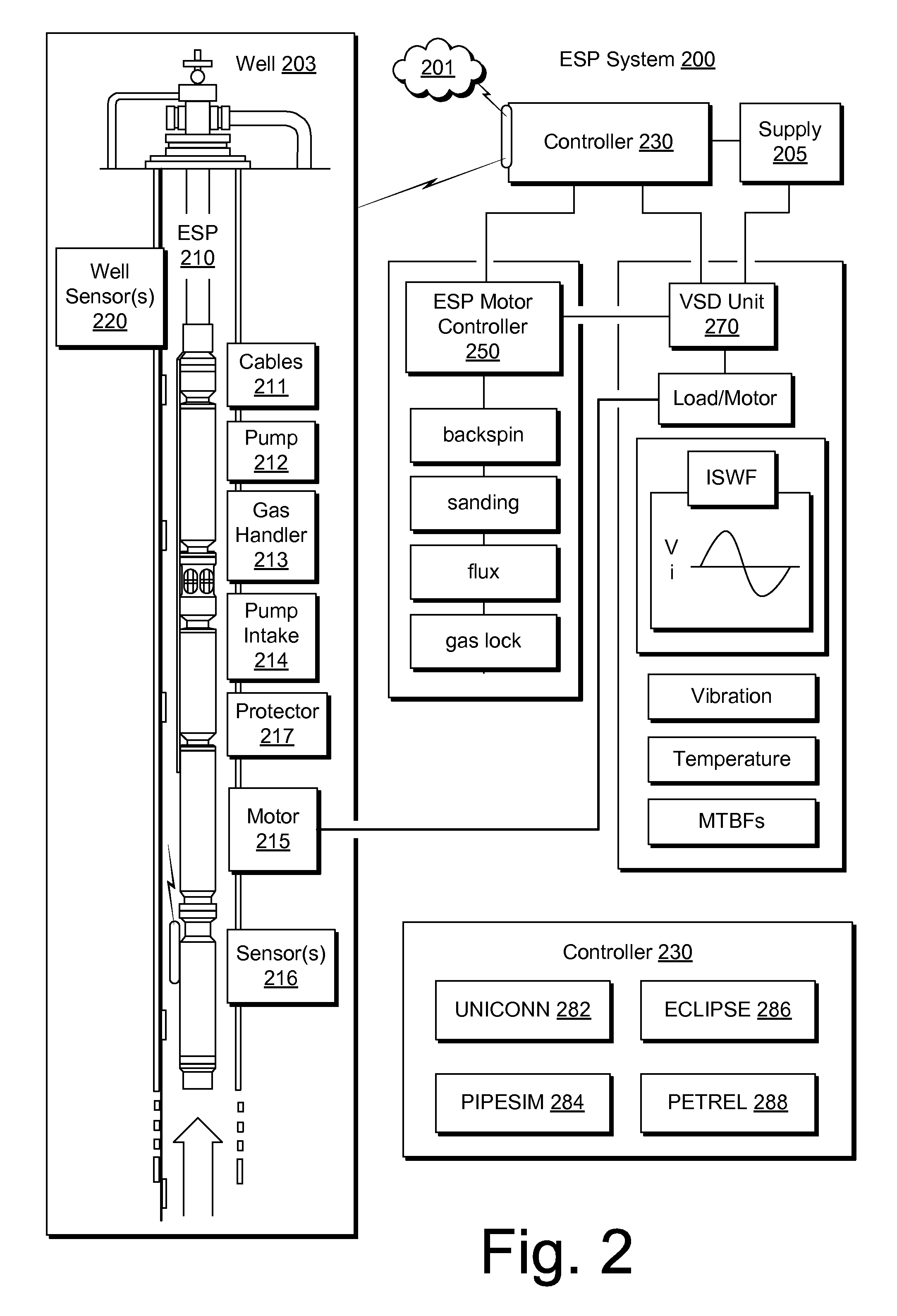
[0025]In high GOR wells, an electric submersible pump (ESP) power cables and motor lead extensions (MLEs) may be exposed to high concentration of corrosive and sour gases and fluids. To protect dielectric layers and copper conductors, metallic lead (Pb) sheaths can be employed as a barrier layer to block permeation of downhole media. However, due to toxicity of free lead (Pb), lead (Pb)...


PUM

PropertyMeasurementUnit
Poweraaaaaaaaaa
Transmissionaaaaaaaaaa
Polymericaaaaaaaaaa

Abstract

A power cable can include a conductor and a layer disposed radially about the conductor where the layer includes graphene nanosheets in a polymeric matrix.

Description

RELATED APPLICATIONS[0001]This application claims priority to and the benefit of a U.S. provisional application having Ser. No. 61 / 873,527, filed 4 Sep. 2013, which is incorporated by reference herein.BACKGROUND[0002]Equipment used in the oil and gas industry may be exposed to high-temperature and / or high-pressure environments. Such environments may also be chemically harsh, for example, consider environments that may include chemicals such as hydrogen sulfide, carbon dioxide, etc. Various types of environmental conditions can damage equipment.SUMMARY[0003]A power cable can include a conductor and a layer disposed radially about the conductor where the layer includes graphene nanosheets in a polymeric matrix. A method can include providing graphene nanosheets in a polymeric matrix as a tape; and wrapping the tape about a conductor. A method can include providing graphene nanosheets in a polymeric matrix; and extruding the graphene nanosheets in the polymeric matrix about a conductor...

Claims


Application Information

Patent Timeline
IPC IPC(8): H01B9/00E21B17/00H01B3/42H01B3/44H01B13/06H01B13/14
CPCH01B9/00H01B13/06E21B17/003H01B3/427H01B3/445H01B13/14H01B3/004E21B43/128E21B43/2406H01B7/046E21B23/00H01B9/02
Inventor XIANG, JINGLEIHOLZMUELLER, JASONMANKE, GREGORY H.
Owner SCHLUMBERGER TECH CORP
Why Eureka
Try Eureka