Absorbent laminate with multiple substrates

a technology of absorbent laminates and substrates, applied in textiles and papermaking, medical science, papermaking, etc., can solve the problem that laminates do not dry the adjacent acquisition layer as well, and achieve the effect of weak tensile strength and higher tensile strength

Active Publication Date: 2016-08-04
EAM
View PDF7 Cites 9 Cited by
  • Summary
  • Abstract
  • Description
  • Claims
  • Application Information

AI Technical Summary

Benefits of technology

[0012]It is contemplated that the third, intermediate substrate layer exhibits a Frazier porosity that is greater than the Frazier porosity of the first and second outer substrate layers by at least about 70 feet3/minute/foot2, more preferably by at least about 100 feet3/minute/foot2, and more preferably by about 150 feet3/minute/foot2. The less porous outer substrate layers tend to be higher in tensile strength, and as a result, this structure leaves two of these stronger layers in place, maintaining the tensile strength of the laminate at a similar level as a laminate comprising the outer layers without the highly porous intermediate substrate layer, which tends to be relatively weak in tensile.
[0013]By configuring the present laminate layers to exhibit the above-described absolute and differential porosity, the function of efficient extraction of fluid from adjacent layers by the laminate is promoted, while the structure still exhibits des

Problems solved by technology

One shortcoming of absorbent laminates such as this, however, is that it has been observed that despite the high SAP content and SAP percentage by weight made

Method used


Image

  • Absorbent laminate with multiple substrates
  • Absorbent laminate with multiple substrates
  • Absorbent laminate with multiple substrates

Examples


example 1

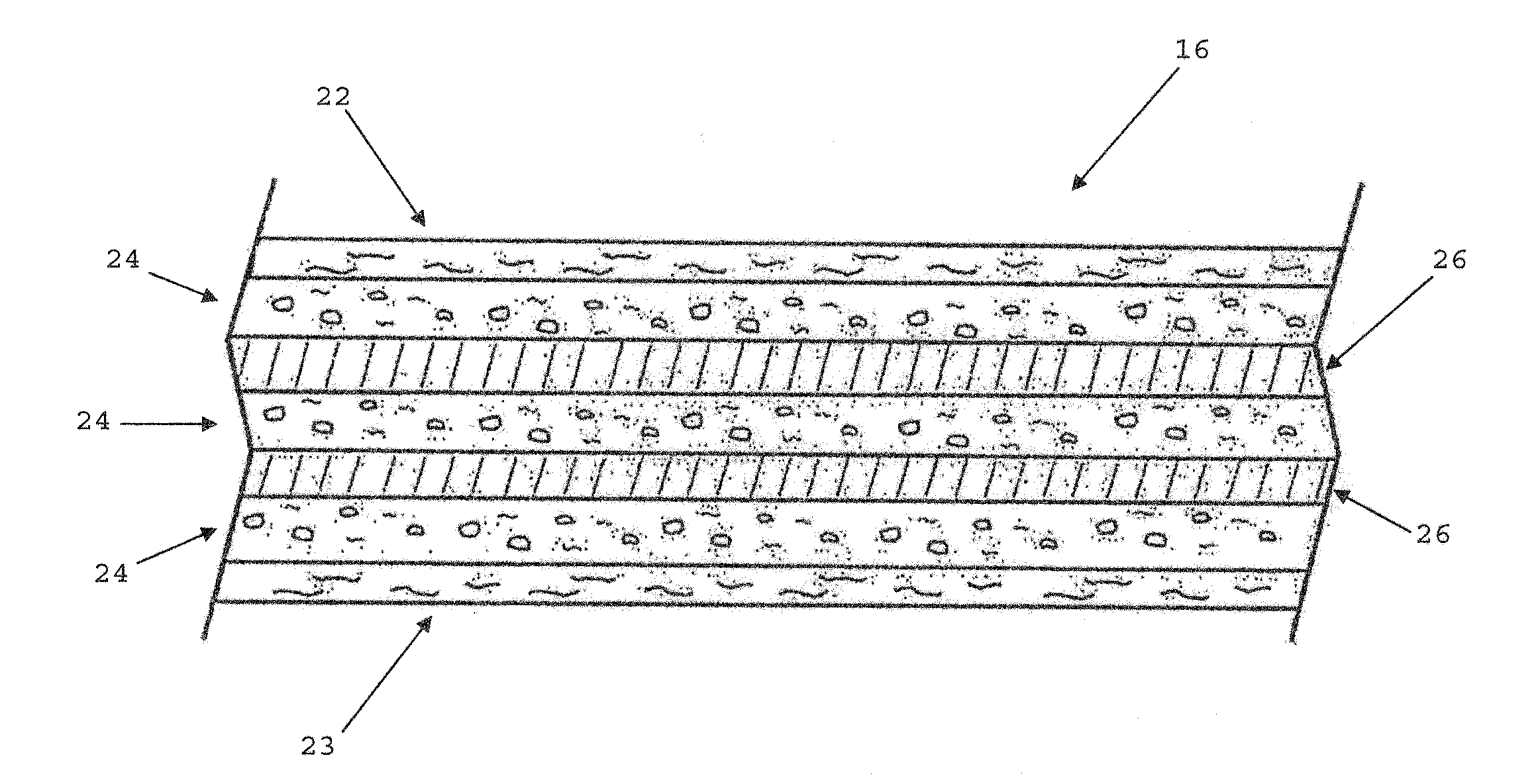
[0046]A laminate of the present invention was made as described above using 17 gsm 3995 tissue from Dunn Paper as the facing layers, and 17 gsm 3008 tissue from Dunn Paper as the highly porous middle layer. The first and second layers of SAP disposed between the highly porous center tissue and the first or second facing tissue layers each contained roughly 35 gsm of SA65s from Sumitomo Seika and each layer was mixed with approximately 2 gsm E60W hot melt adhesive fibers from Savare, ejected by an ITW Dynatec UFD Dynafiber glue applicator head. The resulting material had a basis weight target of 125 gsm, and a SAP content target of around 70 gsm. The highly porous tissue layer material has a Frazier Porosity of around 350 cu ft / min / sq ft. The facing layers have a Frazier Porosity of around 210 cu ft / min / sq ft. A trial sample of the material of Example 1 had an average tensile strength of 15N / 50 mm and an average caliper of 0.97 mm.

example 2

[0047]A laminate of the present invention was made as described in Example 1 above using similar materials and steps, except the SAP content was around 38 gsm in each SAP layer, and the highly porous middle layer was made from 1113 Creped Wadding commercially available from Dunn Paper, and elongated under tension in the machine direction pulling the crepe out of the tissue thus opening the holes in the sheet until it had a basis weight of around 17 gsm. While Frazier porosity data is not available for this elongated creped wadding, a piece of 3008 tissue of the type used in Example 1 above was supported by 18 mesh window screen placed over the hose end of a shop vacuum and the available vacuum drawn through the sample produced a 4.7-inch H2O pressure drop read on a Magnahelic gauge. The 3008 tissue sample was replaced by a sample of 1113 tissue, elongated as described in example 2 and this yielded a pressure drop of 2.0 inches H2O, suggesting the elongated 1113 tissue is more porous...


PUM

PropertyMeasurementUnit
Lengthaaaaaaaaaa
Permeabilityaaaaaaaaaa
Transport propertiesaaaaaaaaaa

Abstract

The present invention relates to an absorbent laminate structure, and disposable absorbent article incorporating the structure, wherein first and second absorbent matrices comprising particulate superabsorbent polymeric material and filamentary adhesive are arranged between two outer substrate layers. The relatively porous, intermediate or central substrate layer, positioned between the absorbent matrices, promotes liquid transport within the laminate structure.

Description

CROSS-REFERENCE TO RELATED APPLICATIONS[0001]This is a non-provisional application claiming priority to U.S. Provisional Ser. No. 62 / 111,377, filed on Feb. 3, 2015 and U.S. Provisional Ser. No. 62 / 148,518, filed on Apr. 16, 2015, both entitled “Absorbent Laminate With Multiple Substrates”, both of which are hereby incorporated by reference in their entirety.TECHNICAL FIELD[0002]The present invention relates generally to an absorbent laminate suited for use in disposable absorbent products, and more particularly to a layered absorbent laminate comprising absorbent matrices of particulate superabsorbent polymer and filamentary adhesive, with a central substrate exhibiting relatively high porosity to promote liquid distribution within the laminate.BACKGROUND OF THE INVENTION[0003]Disposable absorbent articles such as sanitary napkins, diapers, pantiliners, and adult incontinence products have become thinner and more garment-like. To produce thin, flexible absorbent structures with the ...

Claims


Application Information

Patent Timeline
IPC IPC(8): A61F13/539A61L15/62A61L15/42A61L15/28
CPCA61F13/539A61L15/28A61F2013/53908A61L15/425A61L15/62A61F13/534A61F2013/53445A61L15/58A61L15/60D21H27/32D21H27/34D21H27/38
Inventor DUCKER, PAUL M.
Owner EAM
Why Eureka
Try Eureka