
Method and device for sensory control of hybrid operation machine

a technology of hybrid construction machine and sensory control, which is applied in the direction of soil shifting machine/dredger, transportation and packaging, propulsion parts, etc., can solve the problems of high attention, low efficiency, and inability to disclose the precise control that is present between the acceleration pedal and the acceleration pedal, so as to maximize the regenerative energy, increase convenience and safety, and increase energy efficiency

Active Publication Date: 2016-08-04
VOLVO CONSTR EQUIP AB
View PDF0 Cites 4 Cited by
  • Summary
  • Abstract
  • Description
  • Claims
  • Application Information

AI Technical Summary

Benefits of technology

This patent describes a hybrid construction machine that improves safety and convenience for low-speed operations by controlling the electric motor used in its drive system. It also maximizes the energy efficiency by capturing and reusing the energy lost during deceleration of the motor.

Problems solved by technology

The Korean Patent Laid-Open Publication No. 10-2008-0054531 discloses that only the acceleration pedal is used to select the forward or backward traveling of the loader to perform a traveling operation, but does not disclose a precise control that is present between the acceleration pedal and the actual traveling operation.
However, there is a disadvantage in that the detailed operation performed during the low speed traveling thereof depends upon only a skilled operator's feeling.
Accordingly, in the case where a detailed traveling operation is repeatedly performed, the operator requires a very high attention, and thus he or she easily feels a fatigue, thereby causing a safety accident.
In addition, the conventional construction loader entails a shortcoming in that a traditional mechanical brake used upon the deceleration thereof consumes the kinetic energy of the loader as heat of a brake disc, thereby resulting in a deterioration of energy consumption efficiency.
In addition, the conventional hybrid system has a problem in that since it generates regenerative energy using a braking force that is previously set and fixed in the braking operation, there is a limitation in the amount of the regenerative energy generated through the deceleration of the construction machine.

Method used


Image

  • Method and device for sensory control of hybrid operation machine
  • Method and device for sensory control of hybrid operation machine
  • Method and device for sensory control of hybrid operation machine

Examples


Embodiment Construction

[0015]The terms or words used in the specification and the claims of the present invention should not be construed as being typical or dictionary meanings, but should be construed as meanings and concepts conforming to the technical spirit of the present invention on the basis of the principle that an inventor can properly define the concepts of the terms in order to describe his or her invention in the best way.

[0016]Hereinafter, preferred embodiments of the present invention will be described in detail with reference to the accompanying drawings.

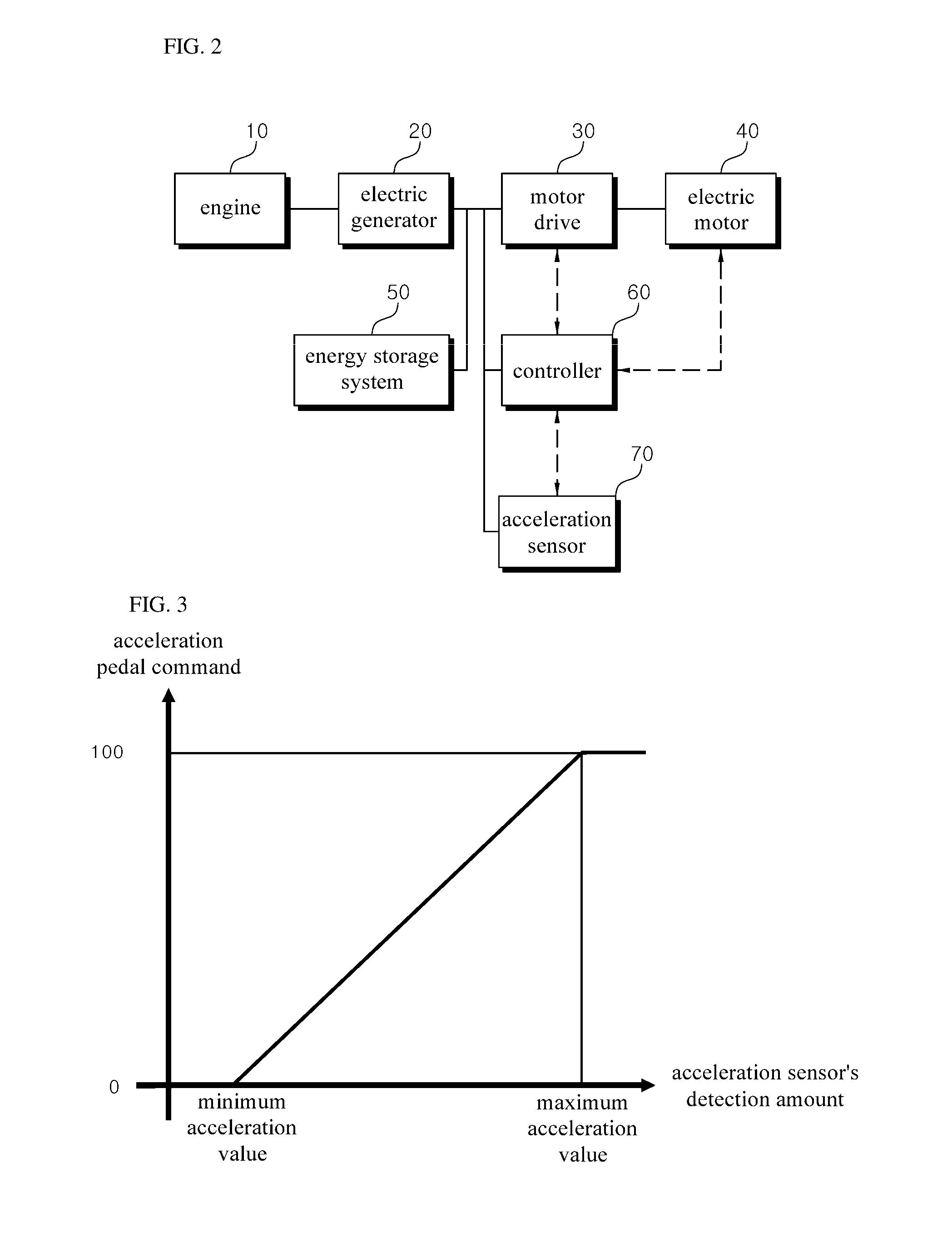
[0017]FIG. 2 is a block diagram showing a schematic configuration of a hybrid construction machine in accordance with an embodiment of the present invention.

[0018]The construction machine of the present invention uses a hybrid system as a power source. The drive mechanism of the hybrid system is as follows. An engine 10 is driven to cause an electric generator 20 to produce electric energy. The produced electric energy drives an electric m...


PUM


Abstract

The present invention relates to a hybrid operation machine of which an electric motor is driven by at least one among a power generator driven by an engine and an energy storage system for storing regenerative energy, and comprising: a motor drive for driving the electric motor; an acceleration sensor for sensing an accelerator pedal command; and a control unit for mapping the accelerator pedal command to a speed command during a low speed traveling operation and controlling a traveling unit through the motor drive, wherein the control unit controls the acceleration and deceleration of the electric motor according to the mapped speed command and generates regenerative energy according to the deceleration of the electric motor.

Description

TECHNICAL FIELD[0001]The present invention relates to a method for controlling a hybrid construction machine and the hybrid construction machine controlled by the same. More particularly, the present invention relates to a sensibility control method for precisely controlling the work and the acceleration and deceleration of the traveling of a hybrid construction machine, and to a hybrid construction machine that effectively generates a regenerative energy using the same.BACKGROUND OF THE INVENTION[0002]Korean Patent Laid-Open Publication No. 10-2008-0054531 discloses a traveling apparatus for a wheel loader. The traveling apparatus includes an acceleration pedal that is provided with a first hall sensor and a second hall sensor, which are disposed at a lower portion thereof and generate a signal for forwardly or backwardly moving the wheel loader, a loader controller that receives the signal generated from the first hall sensor and the second hall sensor of the acceleration pedal an...

Claims


Application Information

Patent Timeline
Patent Type & Authority Applications(United States)
IPC IPC(8): B60L15/20B60W20/00B60L7/10
CPCB60W10/08B60W20/00B60W2510/081B60W2510/082Y10S903/906B60L15/20B60W2540/10B60W2710/082B60L7/10B60K6/46B60W30/18063B60W2300/17E02F9/2075E02F9/2091E02F9/2253Y02T10/72Y02T10/62
Inventor KIM, CHONG-CHUL
Owner VOLVO CONSTR EQUIP AB
Learn More