Air tightness detection device for aluminum alloy wheel hub and method for detecting air tightness of wheel hub

Active Publication Date: 2016-08-04
CITIC DICASTAL
View PDF28 Cites 28 Cited by
  • Summary
  • Abstract
  • Description
  • Claims
  • Application Information

AI Technical Summary

Benefits of technology

[0027]The present invention discloses air tightness detection equipment for an aluminum alloy wheel hub and a detection method thereof, which is characterized in that the air tightness detection equipment comprises leveling ground screws 1, a base 2, precision air pressure sensors 3, a lower clamp 4, a cone cylinder pressure plate 5, air pipes 6, an aluminum alloy wheel hub 7, a pressure plate 8, an upper clamp 9, guide posts 10, an air inlet pipe 11, a compressed airservo control and detection system 12, a servo motor loading control system 13, a loading lead screw 14, a fixed crossed beam 15, and a servo motor and reduction gear 16. The air tightness detection equipment has the following advantages that (1) a support seat and a loading force value are ensured to keep vertical to the ground through the leveling ground screws to ensure an accurate and reliable detection process; (2) the compressed air servo control and detection system can realize two detection manners, i.e. a pressure difference manner and a flow manner; (3) the stable and reliable sealing and rapid and stable action can be ensured for the wheel hub during detection by adopting the servo motor loading control system; (4) the cone cylinder pressure plate is internally provided with the air pipes along a circumferential direction in a uniform distribution manner and the air pipes are connected

Problems solved by technology

The detection equipment are expensive and the consumption of helium gas is large, leading to high overall cost.
Regarding the water air-tightness detection, water quality becomes worse after long-term continuous detection and needs to be changed, which consumes a large amount of clean water; in addition, a detection process needs to be observed by human eyes, which easily results in missed determination, andmoreover, the detection time is longand the overall efficiency i

Method used


Image

  • Air tightness detection device for aluminum alloy wheel hub and method for detecting air tightness of wheel hub
  • Air tightness detection device for aluminum alloy wheel hub and method for detecting air tightness of wheel hub
  • Air tightness detection device for aluminum alloy wheel hub and method for detecting air tightness of wheel hub

Examples


embodiment 1

s Detection Device for Aluminum Alloy Wheel Hub

[0033]In the following, the air tightness detection device for the aluminum alloy wheel hub is illustrated in detial in combination with the drawings.

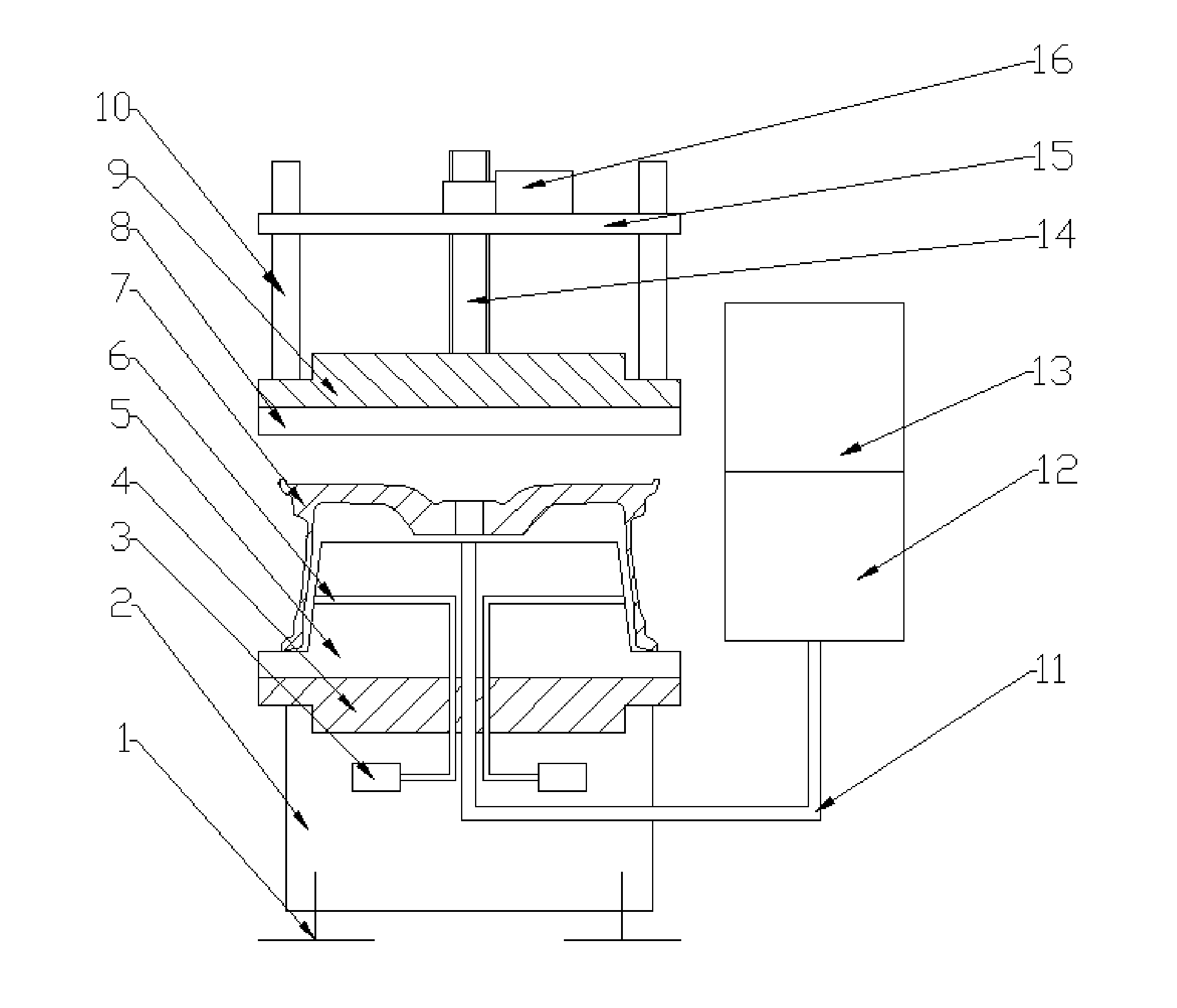
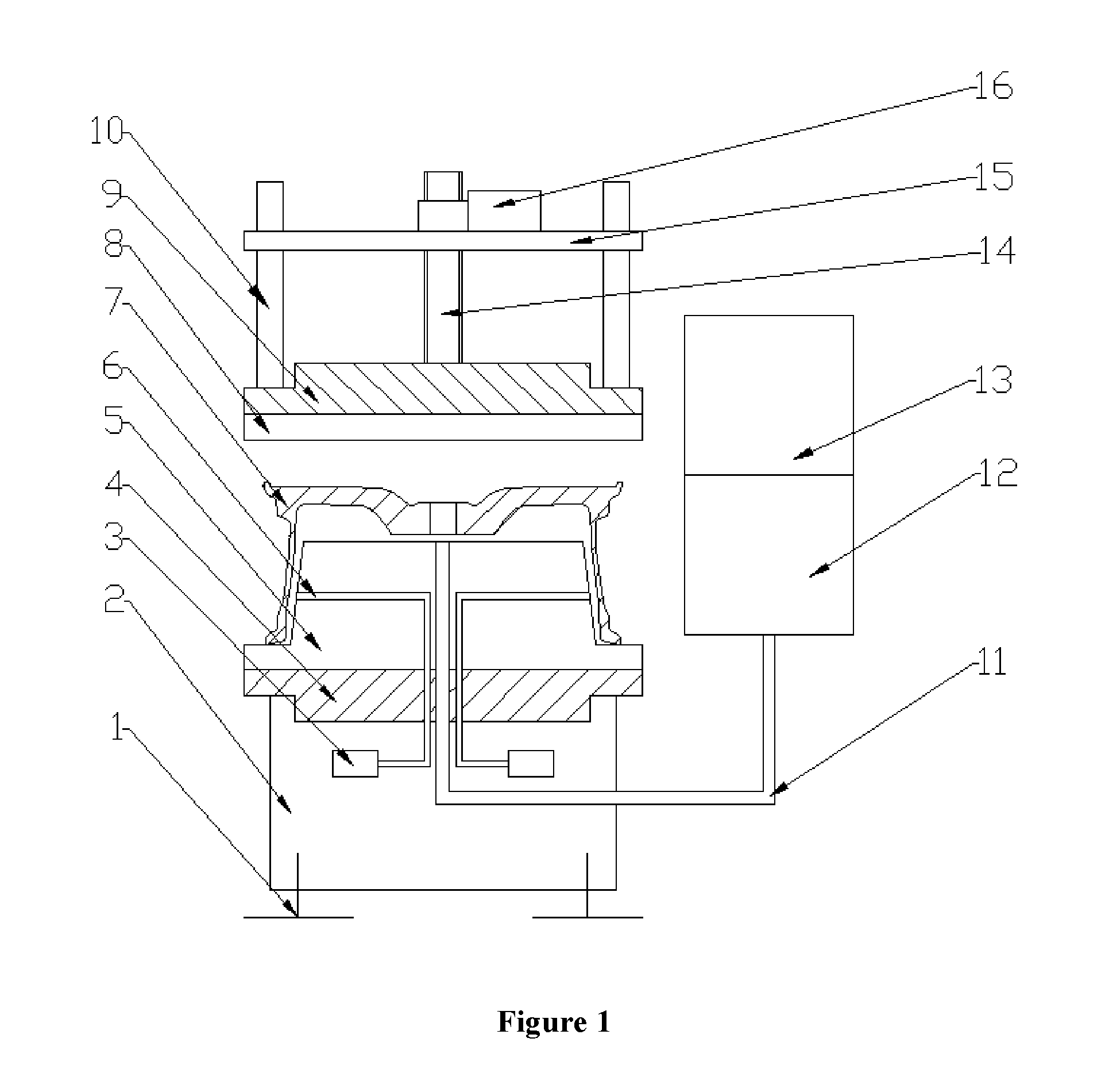
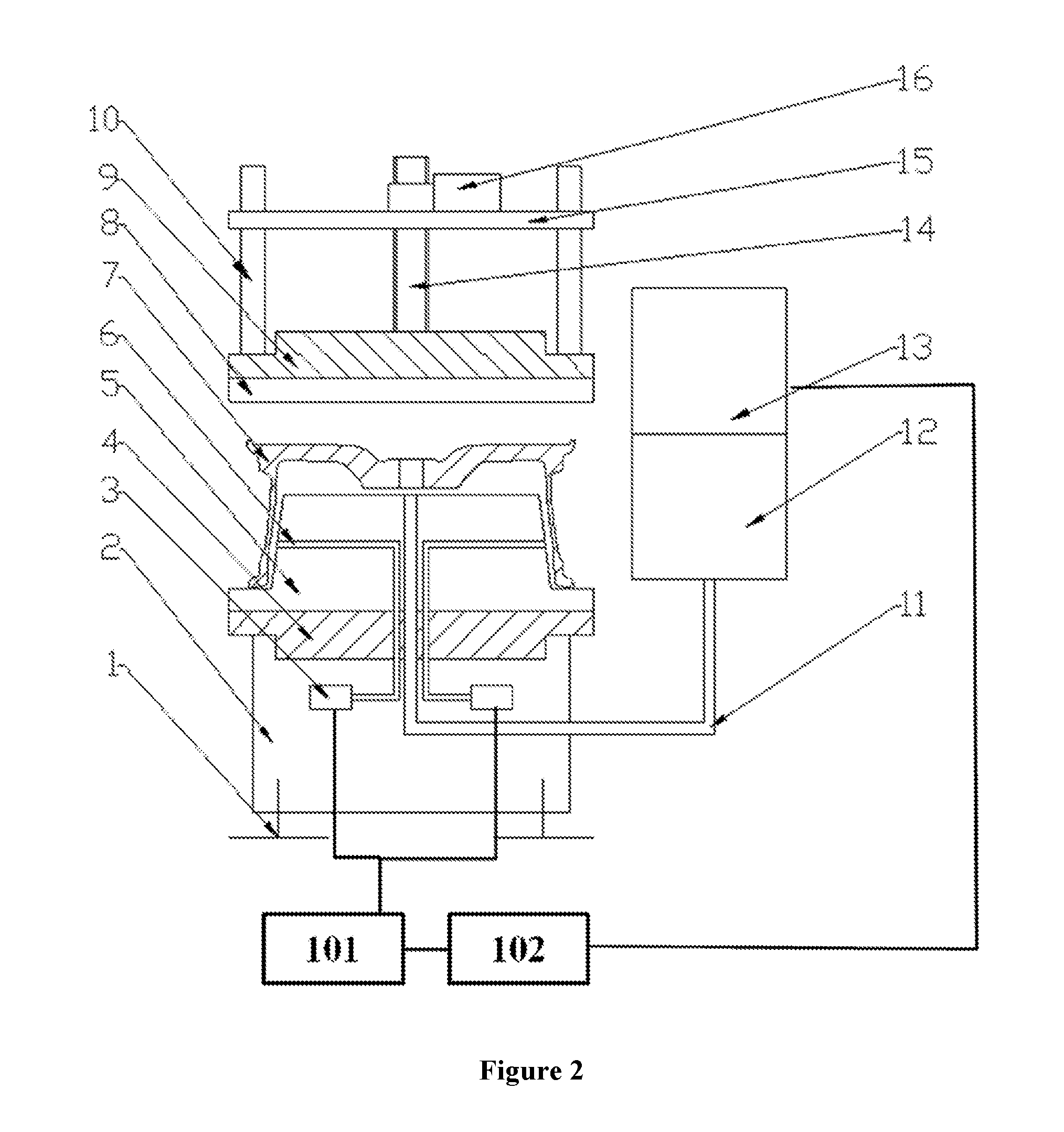
[0034]The air tightness detection device for the aluminum alloy wheel hub comprises leveling ground screws 1, a base 2, precision air pressure sensors 3, a lower clamp 4, a cone cylinder pressure plate 5,air pipes 6, an aluminum alloy wheel hub 7, a pressure plate 8, an upper clamp 9, guide posts 10, an air inlet pipe 11, a compressed air control and detection system 12, a servo motor loading control system 13, a loading lead screw 14, a fixed crossed beam 15, and a servo motor and reduction gear 16.

[0035]The base 2 is kept vertical to the ground through the leveling ground screws 1 and is in stable contact with the ground; the base 2 is provided with sixprecision air pressure sensors 3 and oneair inlet pipe 11, and the sixprecision air pressure sensors are respectively connected with the ...

embodiment 2

Detecting Air Tightness of Aluminum Alloy Wheel Hub-Pressure Difference Method

[0039]As described in Embodiment 1, after the installation of the detection device for the aluminum alloy wheel hub is completed, the wheel hub 7 is placed on the cone cylinder pressure plate 5; the servo motor loading control system 13 controls the servo motor and reduction gear 16 to work; the loading lead screw 14 drives the upper clamp and the pressure plate 8 to move downwards to be in tight press fit with the upper surface of the wheel hub 7, and the sealing process lasts for about 3 seconds.

[0040]Then, the compressed air servo control and detection system 12 fills compressed air with a pressure value of 600 KPa into the sealed inner cavity of the wheel hub 7 through the air inlet pipe 11, and since more than 90% of the inner cavity of the wheel hub 7 is occupied by the cone cylinder pressure plate 5, the inflation process only lasts for 3 to 5 seconds and then can be completed.

[0041]When the six air...

embodiment 3

Detecting Air Tightness of Aluminum Alloy Wheel Hub-Flow Method

[0047]As described in Embodiment 1, after the installation of the detection device for the aluminum alloy wheel hub is completed, the wheel hub 7 is placed on the cone cylinder pressure plate 5; the servo motor loading control system 13 controls the servo motor and reduction gear 16 to work; the loading lead screw 14 drives the upper clamp and the pressure plate 8 to move downwards to be in tight press fit with the upper surface of the wheel hub 7; the sealing process lasts for about 3 seconds.

[0048]Then, the compressed gas control and detection system 12 fills compressed air with a pressure value of 600KPa into the sealed inner cavity of the wheel hub 7 through the air inlet pipe 11; since more than 90% of the inner cavity of the wheel hub 7 is occupied by the cone cylinder pressure plate 5, the inflation process only lasts for 3 to 5 seconds and then can be completed.

[0049]When the six air pipes 6 in uniform distributi...


PUM


Abstract

The present invention provides an air tightness detection device for an aluminum alloy wheel hub, which is characterized by precision air pressure sensors, a lower clamp, a cone cylinder pressure plate, air pipes, a pressure plate, guide posts, an air inlet pipe, and a compressed gas control and detection system. A technical solution of the present invention has the following advantages that the cone cylinder pressure plate of the detection device reduces the space of an inner cavity of the wheel hub to further reduce inflating volume, thereby increasing detection efficiency; the characteristics of readily availability for preparation, no pollution and low cost are achieved by taking compressed air as a leakage indication gas.

Description

TECHNICAL FIELD[0001]The present invention relates to the field of automobile parts, and in particular to air tightness detection device for an aluminum alloy wheel hub and a method for detecting the air tightness of the wheel hub.BACKGROUND ART[0002]The air tightness of an aluminum alloy wheel hub is an important index for measuring the performance of the aluminum alloy wheel hub. In wheel hub manufacturing enterprises, every aluminum alloy wheel hub must be inspected on the conformity with an air tightness requirement.[0003]Common detection methods adopted include a helium gas-tightness detection method and a water air-tightness detection method. When a heliumgas is adopted for detection, an inertgas of heliumgas and a helium mass spectrometer need to be used. The detection equipment are expensive and the consumption of helium gas is large, leading to high overall cost. The principle for thehelium gas-tightness detection is that a wheel hub needs to be placed in an air-tight space...

Claims


Application Information

Patent Timeline
IPC IPC(8): G01M3/26
CPCG01M3/26G01M3/329
Inventor LIU, CHUNHAIYIN, ZHIGAOTANG, DEBINLV, JINQILI, ZHIPENGZHANG, AIGUOZHU, ZHIHUAWANG, YONGNINGLI, CHANGHAI
Owner CITIC DICASTAL
Why Eureka
Try Eureka