Eureka AIR delivers breakthrough ideas for toughest innovation challenges, trusted by R&D personnel around the world.

Photoelectric conversion apparatus, imaging system, and driving method for photoelectric conversion apparatus

a conversion apparatus and photoelectric technology, applied in the field imaging system, driving method of photoelectric conversion apparatus, can solve the problems of reducing the accuracy of detecting excessive charges and in some cases the reduction of autofocus accuracy

Inactive Publication Date: 2016-08-04
CANON KK
View PDF1 Cites 6 Cited by
  • Summary
  • Abstract
  • Description
  • Claims
  • Application Information

AI Technical Summary

Benefits of technology

The present invention is a photoelectric conversion apparatus that includes a pixel unit with a plurality of pixels. Each pixel has a photoelectric conversion unit that generates charges in response to incident light and a charge transfer unit that transfers the charges to a charge accumulation unit. An amplification unit outputs an output voltage based on the charges accumulated in the charge accumulation unit. A reference voltage generation unit generates a reference voltage. A comparison unit compares the output voltage with the reference voltage and outputs a comparison result. A control unit controls the timing to end the accumulation of the charges in the photoelectric conversion unit based on the comparison result. This invention allows for improved accuracy in detecting and measuring the light incident on the photoelectric conversion apparatus.

Problems solved by technology

In this case, depending on a scene to be photographed, due to an erroneous determination of the charges accumulated by the dark current generated in the charge-voltage conversion unit as the excessive charges and other such factors, an accuracy of detecting the excessive charges may be reduced, which may lead to a reduction in autofocus accuracy in some cases.

Method used


Image

  • Photoelectric conversion apparatus, imaging system, and driving method for photoelectric conversion apparatus
  • Photoelectric conversion apparatus, imaging system, and driving method for photoelectric conversion apparatus
  • Photoelectric conversion apparatus, imaging system, and driving method for photoelectric conversion apparatus

Examples


first embodiment

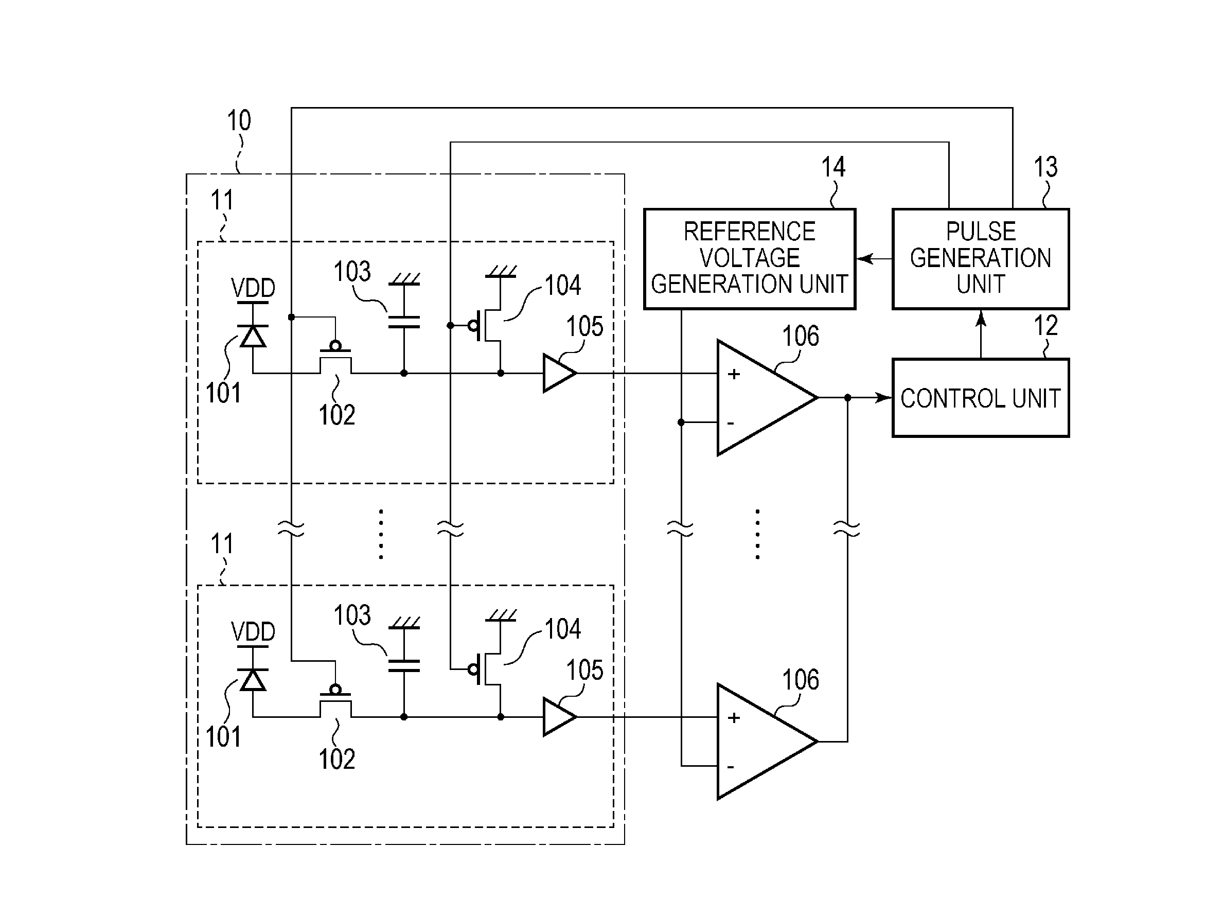
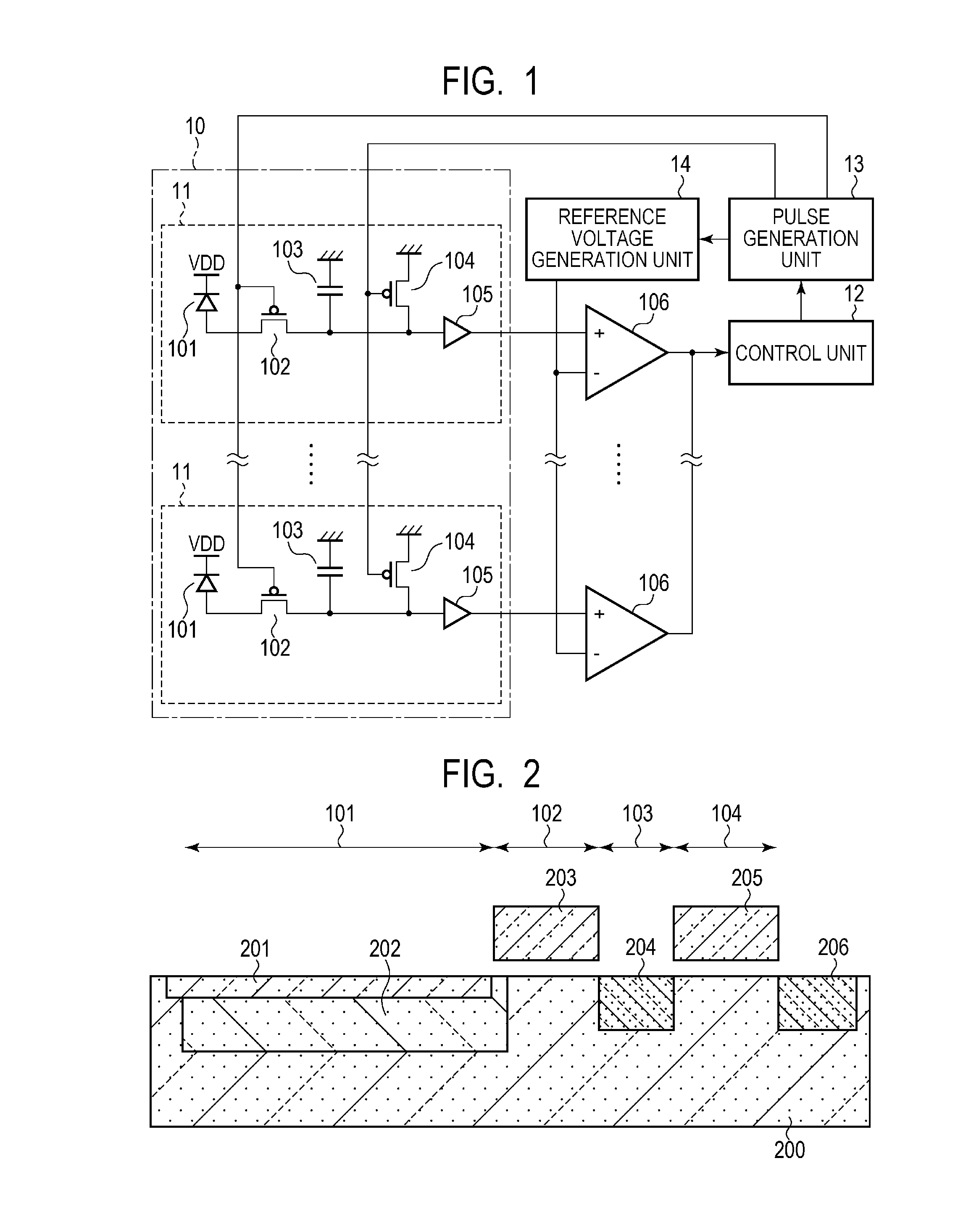
[0022]FIG. 1 is a diagram for illustrating an example of a circuit configuration of a photoelectric conversion apparatus according to a first embodiment of the present invention. The photoelectric conversion apparatus includes a pixel unit 10, a control unit 12, a pulse generation unit 13, a reference voltage generation unit 14, and a plurality of comparators (comparison units) 106. The pixel unit 10 includes a plurality of pixels 11. In this embodiment, the pixels 11 are arranged one-dimensionally, but the present invention is not limited thereto. Each of the pixels 11 includes a photoelectric conversion unit 101, a charge transfer unit 102, a floating diffusion (hereinafter referred to as “FD”) 103, a reset unit 104, and an amplification unit 105. Moreover, the plurality of comparators 106 are provided in correspondence with the plurality of pixels 11, respectively.

[0023]The photoelectric conversion unit 101 is formed of a photodiode having a cathode to which a power supply voltag...

second embodiment

[0065]A second embodiment of the present invention is described. In this embodiment, a configuration in which, in a case where a photoelectric conversion apparatus includes a plurality of pixel units, the reference voltage input to the comparator of each of the pixel units is different is adopted. A description on components similar to those of the first embodiment is omitted.

[0066]FIG. 6 is a diagram for illustrating an example of a circuit layout of the photoelectric conversion apparatus according to the second embodiment. A photoelectric conversion apparatus 60 includes pixel units 61 and 62, the comparator 106, the control unit 12, the pulse generation unit 13, and reference voltage generation units 63 and 64. Moreover, each of the pixel unit 61 and the pixel unit 62 includes a plurality of pixels 11 arranged one-dimensionally. The reference voltage generation unit 63 is configured to supply a first reference voltage to the comparators 106 connected to the pixel unit 61, and the...

third embodiment

[0072]A third embodiment of the present invention is described. In this embodiment, a configuration in which the reference voltage is changed depending on a temperature of a photoelectric conversion apparatus is adopted. A circuit configuration is similar to that of the first embodiment illustrated in FIG. 1, and hence a description thereof is omitted.

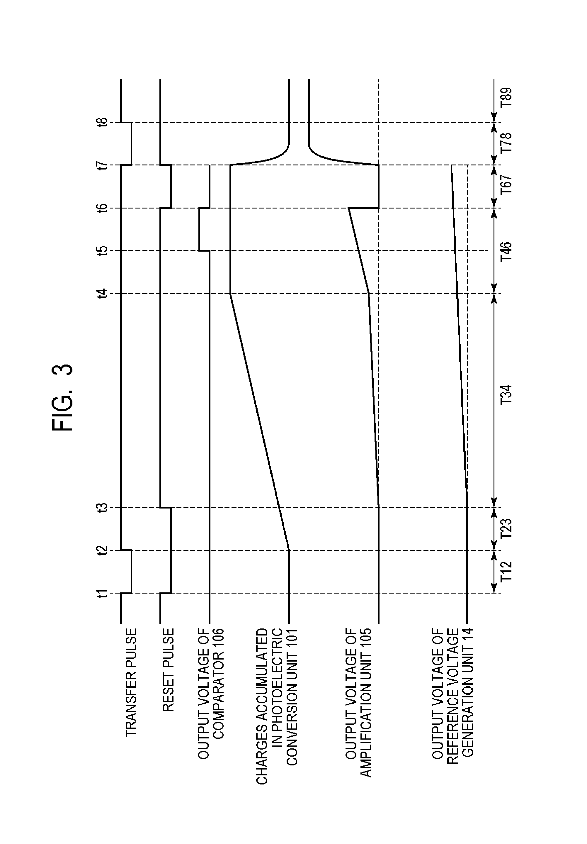
[0073]FIG. 9 is a timing chart for illustrating relationships of respective pulses, output voltages, and the like of the photoelectric conversion apparatus according to the third embodiment. The same times and periods are denoted by the same reference symbols as those of FIG. 3. This timing chart is different from FIG. 3 in that, in period T34, depending on the temperature of the photoelectric conversion apparatus, the output of the amplification unit 105 and the output voltage of the reference voltage generation unit 14 are different. For a reason similar to that described in the second embodiment, the dark current becomes larger as t...


PUM


Abstract

Provided is a photoelectric conversion apparatus, including: a plurality of pixels, each of the plurality of pixels including: a photoelectric conversion unit; a charge transfer unit; and an amplification unit; a reference voltage generation unit; a comparison unit configured to output a comparison result by comparing an output voltage from the amplification unit and a reference voltage output from the reference voltage generation unit; and a control unit configured to control a timing to end the accumulation of the charges in the photoelectric conversion unit based on the comparison result, in which the reference voltage to be compared with the output voltage based on the charges transferred from the photoelectric conversion unit to the charge accumulation unit when the charge transfer unit is in a non-conductive state, is a voltage corresponding to charges accumulated in the charge accumulation unit due to a dark current.

Description

BACKGROUND OF THE INVENTION[0001]1. Field of the Invention[0002]The present invention relates to a photoelectric conversion apparatus, an imaging system, and a driving method for the photoelectric conversion apparatus.[0003]2. Description of the Related Art[0004]In Japanese Patent Application Laid-Open No. 2009-130396, a photoelectric conversion apparatus used for phase-difference detection auto focusing is described. This photoelectric conversion apparatus is configured to monitor an accumulation amount of photocharges generated in a photoelectric conversion unit such as a photodiode, and automatically control accumulation time of charges in consideration of a dynamic range of a circuit. This photoelectric conversion apparatus has a structure in which excessive charges overflowed from the photoelectric conversion unit to a charge-voltage conversion unit such as a floating diffusion are monitored to control the accumulation time of the charges. In this manner, a signal of a level su...

Claims


Application Information

Patent Timeline
Patent Type & Authority Applications(United States)
IPC IPC(8): G03B13/36G01J1/42G01J1/44
CPCG03B13/36G01J1/4209G01J1/44H04N25/76H04N25/633H04N25/53H04N25/63
Inventor KUSUSAKI, TOMOKI
Owner CANON KK
Why Eureka
Eureka Blog
Learn More