
Lubrication system for internal combustion engine

Active Publication Date: 2016-08-11
HONDA MOTOR CO LTD
View PDF47 Cites 4 Cited by
  • Summary
  • Abstract
  • Description
  • Claims
  • Application Information

AI Technical Summary

Benefits of technology

The purpose of this invention is to create a lubrication system for an internal combustion engine that can supply lubricating oil to all parts of the engine and recover any lubricating oil that may accumulate on the walls. This should be done with a simple structure.

Problems solved by technology

However, the need for an oil pump for supplying lubricating oil inevitably increases the size and complexity of the engine so that the engine may not be commercially acceptable for use as a general purpose engine.
When such deposited lubricating oil is sucked into the combustion chamber in any substantial amount, the resulting combustion of the lubricating oil may cause an increase in THC (total hydrocarbon content) in the emission, generation of white smoke and abnormal combustion.

Method used


Image

  • Lubrication system for internal combustion engine
  • Lubrication system for internal combustion engine
  • Lubrication system for internal combustion engine

Examples


Embodiment Construction

)

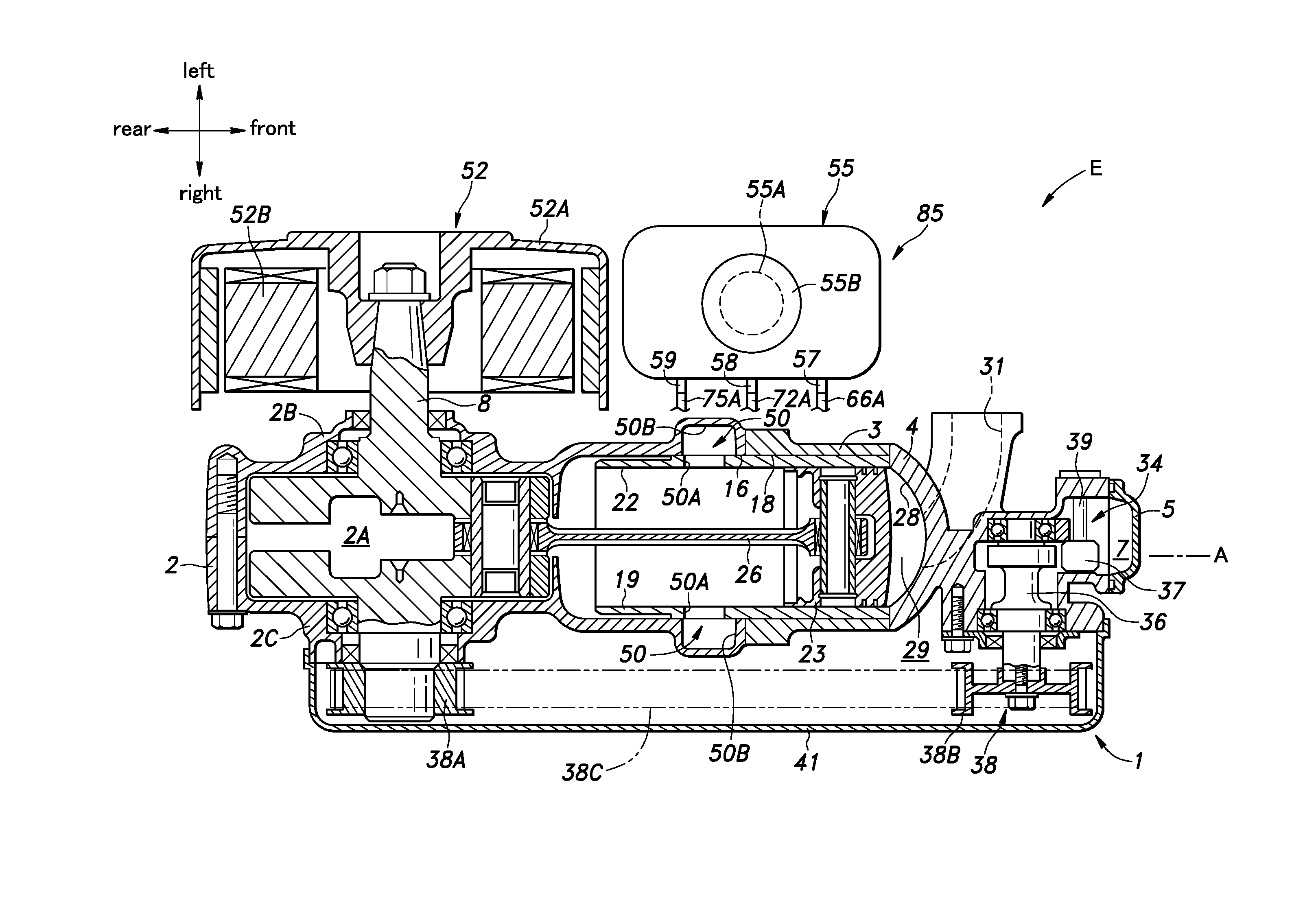
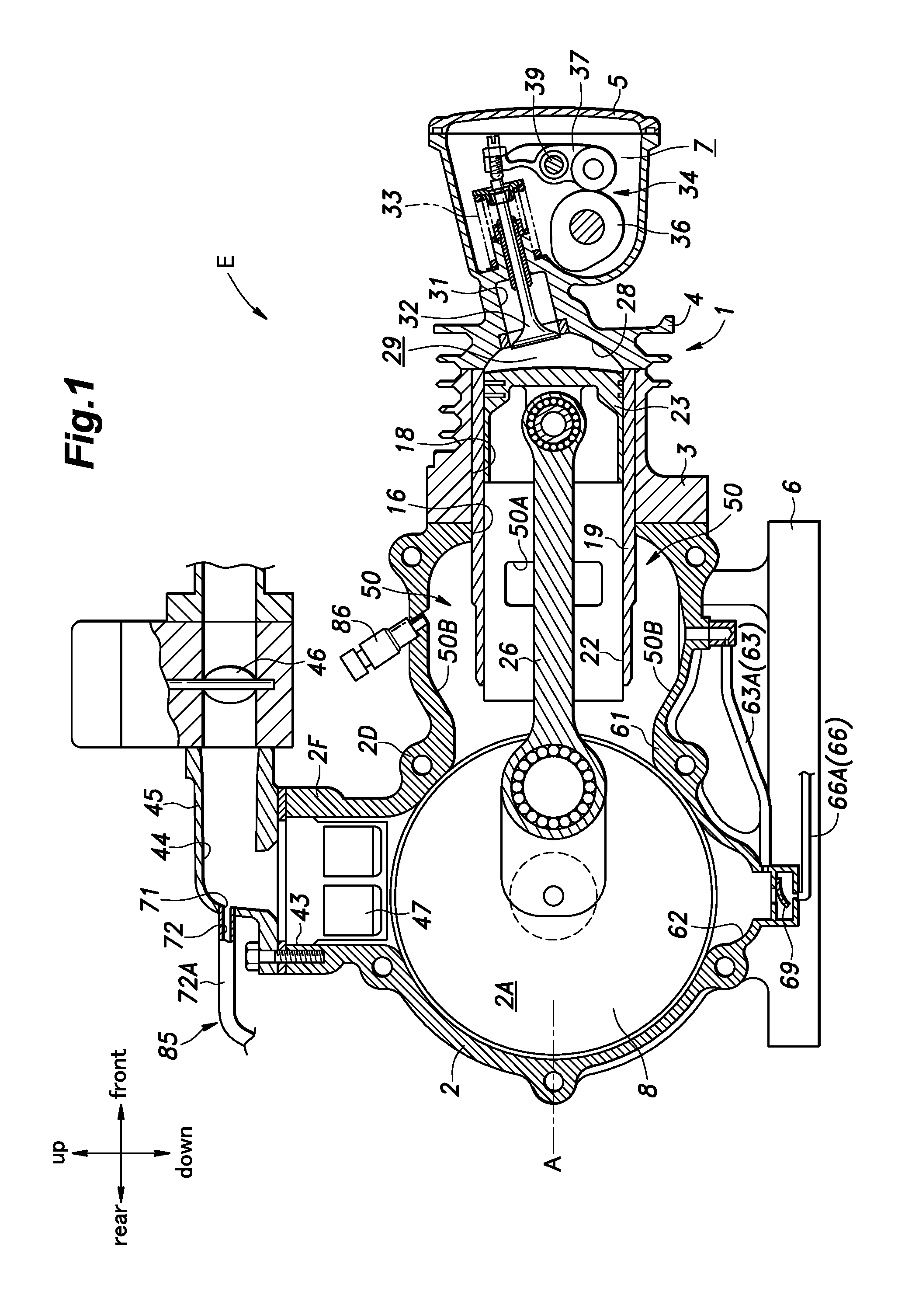
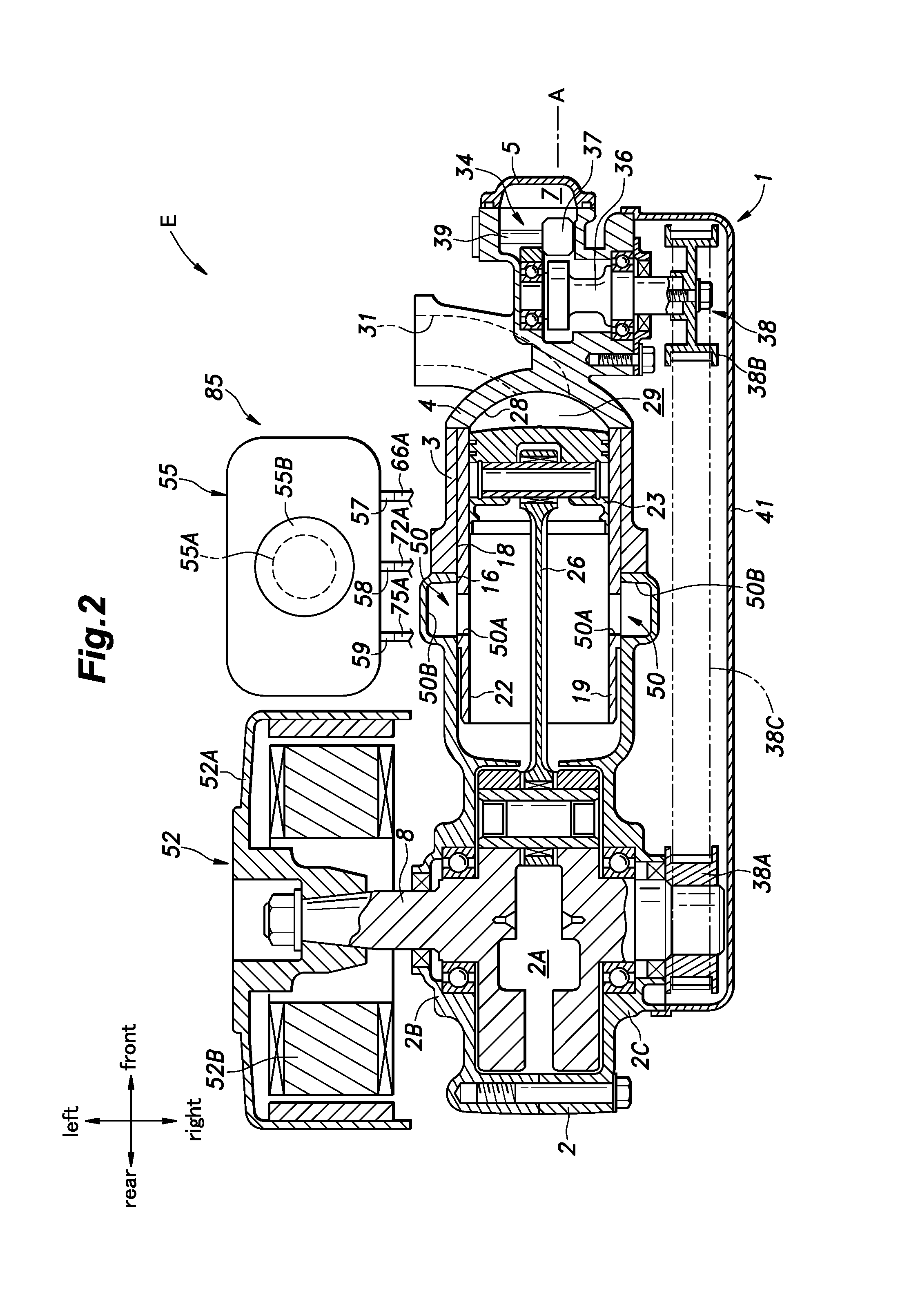
[0029]The present invention is described in the following in terms of a preferred embodiment consisting of a single cylinder, uni-flow two stroke engine (engine E) with reference to the appended drawings. In the illustrated embodiment, the engine E is used for powering an electric generator.

[0030]As shown in FIGS. 1 and 2, an engine main body 1 of the engine E includes a crankcase 2 defining a crankcase chamber 2A therein, a cylinder block 3 connected to the front end of the crankcase 2, a cylinder head 4 connected to the front end of the cylinder block 3 and a head cover 5 connected to the front end of the cylinder head 4 and defining a valve actuation chamber 7 in cooperation with the cylinder head 4. The engine main body 1 extends in the fore and aft direction, and is provided with a horizontal cylinder axial line A extending in the fore and aft direction. The lower surface of the crankcase 2 is attached to a base 6 for supporting the engine main body 1 in this horizontal orient...


PUM


Abstract

A lubrication system for an engine is provided which includes an oil tank, a first passage communicating a bottom part of the crankcase chamber with an upper part of the oil tank, a first check valve provided in the first passage to permit a flow from the crankcase chamber to the oil tank but not in a reverse direction, a second passage communicating an upper part of the oil tank with an upper part of the crankcase chamber, a second check valve provided in the second passage to permit a flow from the oil tank to the crankcase chamber but not in a reserve direction and a third passage communicating a lower part of the oil tank with the second passage.

Description

TECHNICAL FIELD[0001]The present invention relates to a lubrication system for an internal combustion engine.BACKGROUND ART[0002]In the field of two stroke engines, it is known to mix lubricating oil in mist form with the intake mixture in order to lubricate various sliding parts of the engine which are exposed to the mixture. Mixing lubricating oil with the fuel may be accomplished by mixing the lubricating oil with the liquid fuel which is then injected into the intake air or by spraying oil mist into the intake air separately from the fuel. For instance, JP2014-20314A discloses an arrangement where lubricating oil stored in an oil tank is fed to and injected into an intake passage by using a diaphragm oil pump.[0003]However, the need for an oil pump for supplying lubricating oil inevitably increases the size and complexity of the engine so that the engine may not be commercially acceptable for use as a general purpose engine. Furthermore, when lubricating oil is injected into an ...

Claims


Application Information

Patent Timeline
IPC IPC(8): F01M11/02
CPCF01M2011/022F01M11/02F01M1/04F16N7/34F16N19/00F01M1/08F01M1/14F01M2001/083F16N2200/08
Inventor KURATA, MASHU
Owner HONDA MOTOR CO LTD
Learn More