Rotation sensor

a technology of rotation sensor and rotor, which is applied in the direction of speed/acceleration/shock measurement, measurement devices, instruments, etc., can solve the problems of not being able to control the rotation state of the rotator with high accuracy

Active Publication Date: 2016-08-11
DENSO CORP
View PDF8 Cites 4 Cited by
  • Summary
  • Abstract
  • Description
  • Claims
  • Application Information

AI Technical Summary

Benefits of technology

[0005]The hysteresis comparator circuit has two thresholds, between which the threshold changes depending on the change of an input signal from the magnetoelectric conversion element. More specifically, when the voltage level of the input signal exceeds a threshold (hereinafter referred to as a first threshold), the thresho...

Problems solved by technology

Therefore, it is not possible to control the rotation state of the rotator with high accura...

Method used


Image

  • Rotation sensor
  • Rotation sensor
  • Rotation sensor

Examples


first embodiment

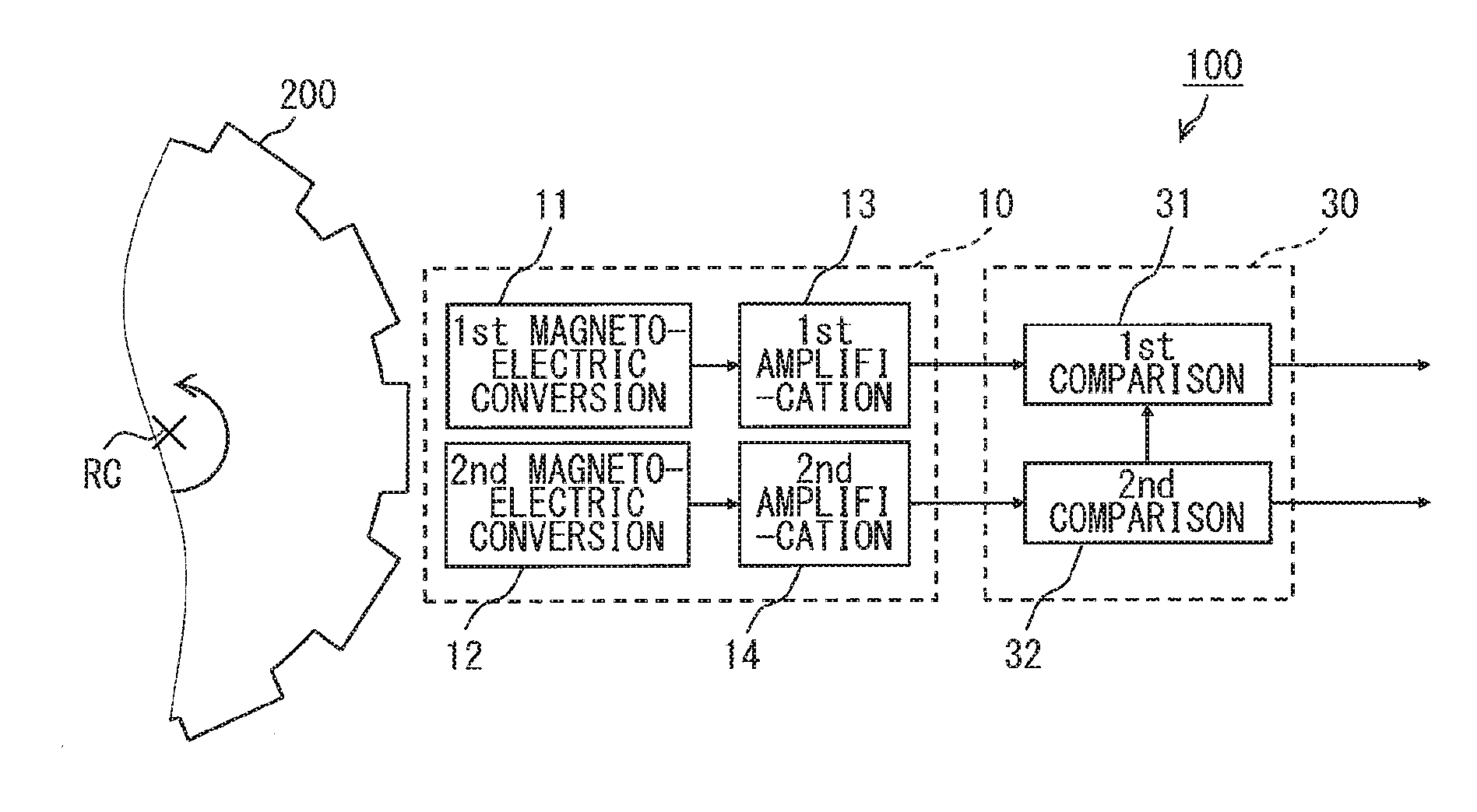
[0026]A rotation sensor according to this embodiment will be described with reference to FIGS. 1 to 4. In a timing chart of FIG. 4, the vertical axis represents voltage, and the horizontal axis represents time. Hereinafter, a direction passing through a rotation center RC of the rotator 200 in one direction is an axial direction, and a direction around the axial direction is a circumferential direction.

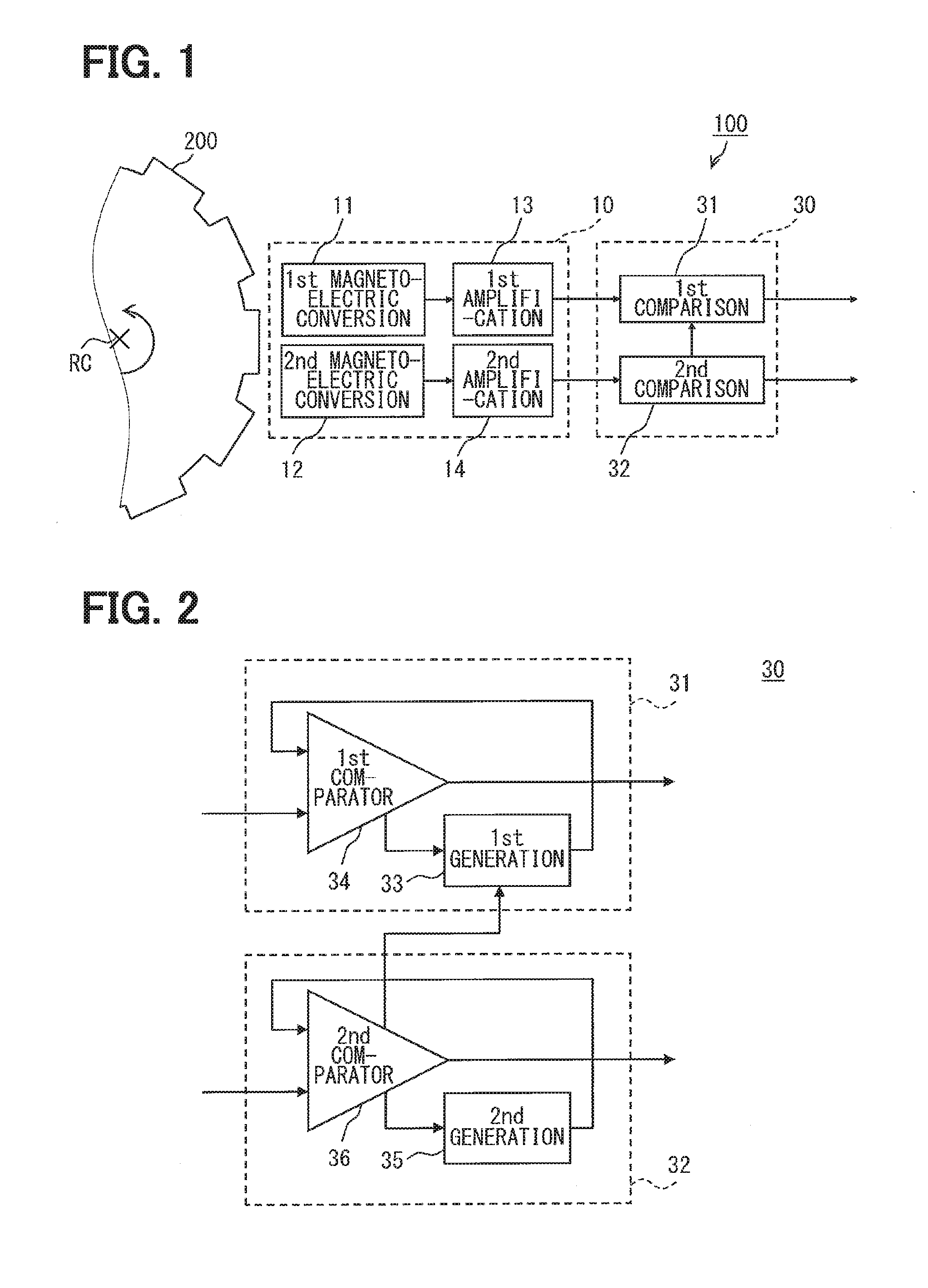
[0027]The rotation sensor 100 detects the rotation state of the rotator 200 based on the change of magnetic flux whose direction changes periodically with the rotation of the rotator 200. As shown in FIG. 1, the rotation sensor 100 has a magnetoelectric conversion unit 10 for converting the change of magnetic flux whose direction changes periodically into an electric signal and a processing unit 30 for processing the electric signal of the magnetoelectric conversion unit 10.

[0028]The magnetoelectric conversion unit 10 has a first magnetoelectric conversion unit 11 and a second magneto...

second embodiment

[0060]Next, a second embodiment of the present disclosure will be described with reference to FIGS. 6 to 9. A rotation sensor according to the second embodiment has a lot in common with that of the above embodiment. Accordingly, hereinafter, common parts will not be described, and different parts will be intensively described. Further, hereinafter, the same elements as in the above embodiment are denoted by the same reference numerals.

[0061]Unlike the rotation sensor 100 according to the first embodiment, the rotation sensor 100 according to this embodiment has a combination unit 60 in addition to the magnetoelectric conversion unit 10 and the processing unit 30, as shown in FIG. 6. The magnetoelectric conversion unit 10 and the processing unit 30 have slightly different configurations from those of the rotation sensor 100 according to the first embodiment. Accordingly, the difference between the configurations and the combination unit 60 as a new constituent element will be sequent...


PUM


Abstract

A rotation sensor has a magnetoelectric conversion unit that converts change of magnetic flux whose direction changes periodically with rotation of a rotator into an electric signal and a processing unit that processes the electric signal. The magnetoelectric conversion unit outputs a first detection signal and a second detection signal. The processing unit has a first comparison unit that compares a detection threshold and the first detection signal and a second comparison unit that compares a reference threshold and the second detection signal. The first comparison unit changes a voltage level of the detection threshold when the first detection signal exceeds or falls below the detection threshold and then restores the voltage level of the detection threshold based on the second detection signal and the reference threshold, and the first comparison unit converts the first detection signal into a pulse signal based on the detection threshold of the same voltage level.

Description

CROSS-REFERENCE TO RELATED APPLICATIONS[0001]The present disclosure is based on Japanese Patent Application No. 2013-147713 filed on Jul. 16, 2013 and Japanese Patent Application No. 2014-20694 filed on Feb. 5, 2014, the disclosures of which are incorporated herein by reference.TECHNICAL FIELD[0002]The present disclosure relates to a rotation sensor for detecting the rotation state of a rotator based on the change of magnetic flux whose direction changes periodically with the rotation of the rotator.BACKGROUND ART[0003]Conventionally, there has been proposed a hysteresis comparator circuit as described in, for example, Patent Literature 1. It can be considered that the hysteresis comparator circuit is used to convert, into a pulse signal, an output signal of a magnetoelectric conversion element for converting the change of magnetic flux whose direction changes periodically with the rotation of the rotator into an electric signal. The hysteresis comparator circuit converts the output...

Claims


Application Information

Patent Timeline
IPC IPC(8): G01P3/487
CPCG01P3/481G01P3/487G01D5/2451G01P3/489G01P3/488
Inventor OHMI, TETSUYA
Owner DENSO CORP
Why Eureka
Try Eureka