Display device and control method for same

a technology of display device and control method, which is applied in the field of display device, can solve the problems of occurrence of delay in image display, inability to solve simultaneous equations in real time, and inability to achieve three-stage region coefficients

Active Publication Date: 2016-08-11
FUJIFILM CORP
View PDF4 Cites 16 Cited by
  • Summary
  • Abstract
  • Description
  • Claims
  • Application Information

AI Technical Summary

Benefits of technology

[0014]An object of the present invention is to provide a display device, which is capable of calculating an optimal setting value for the luminance of emitted light of the light source for each segment region in real time, and a control method for the same.
[0027]According to the display device and the control method of the present invention, it is possible to calculate an optimal setting value for the luminance of emitted light of the light source for each segment region in real time.

Problems solved by technology

However, solving simultaneous equations in real time is difficult in practice, and a method of solving simultaneous equations in real time is not disclosed in JP2007-34251A.
Accordingly, in the liquid crystal display device of JP2007-34251A, there is a concern about occurrence of a delay in image display.
Therefore, in accordance with the image data, any of the region coefficients having three stages may not be appropriate.

Method used


Image

  • Display device and control method for same
  • Display device and control method for same
  • Display device and control method for same

Examples


first embodiment

[0056][Liquid Crystal Display Device of First Embodiment]

[0057]

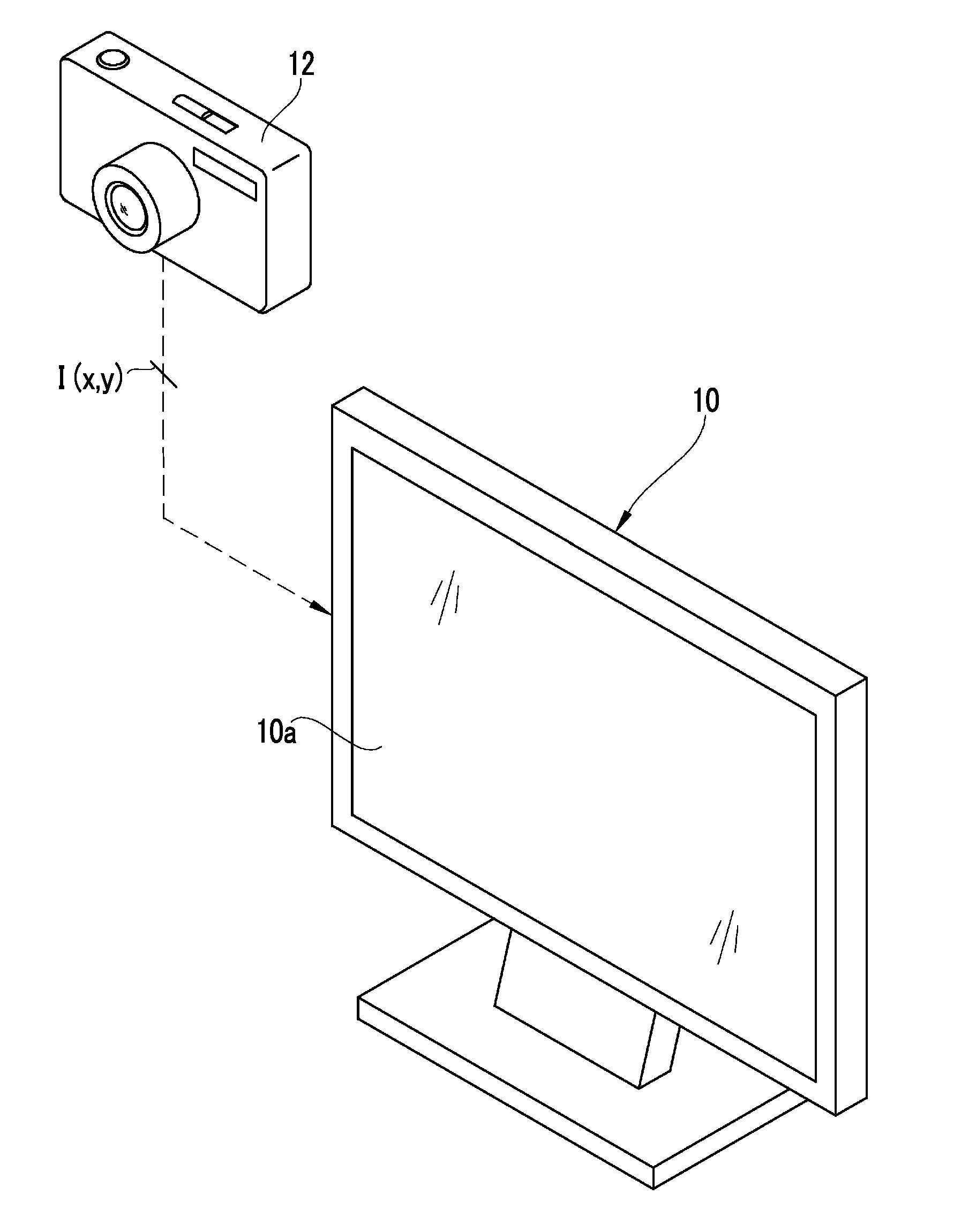
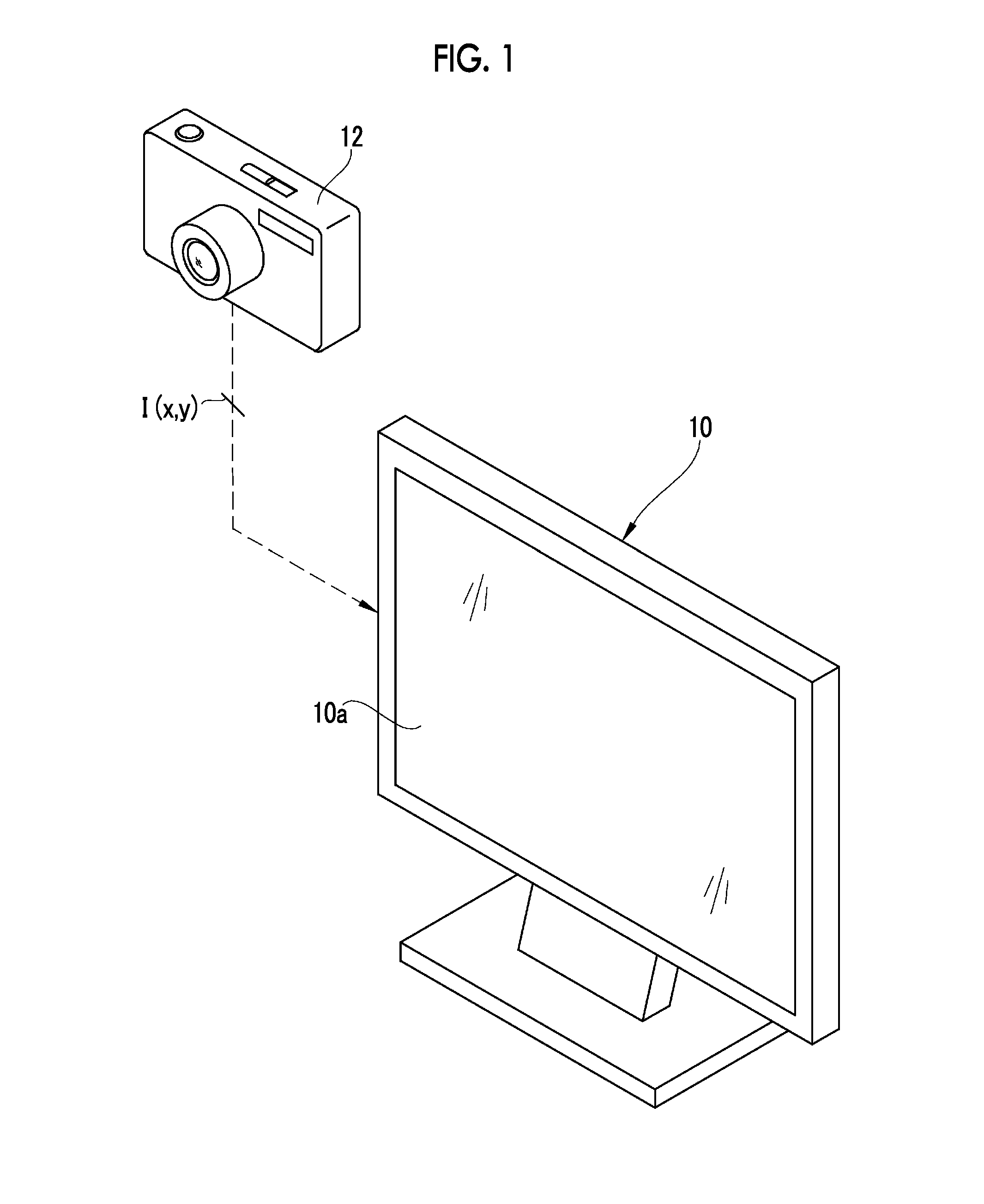
[0058]As shown in FIG. 1, a liquid crystal display device (display device) 10 having a BLD control function acquires image data I(x, y) of a still image or a moving image from a digital camera 12 connected in a wired or wireless manner, and displays the image. Here, coordinates (x, y) mean coordinates of a pixel unit of an image and a liquid crystal panel 15 (refer to FIG. 2). It should be noted that the liquid crystal display device 10 may acquire the image data I(x, y) through a portable terminal, the Internet, television broadcast, and the like, instead of the digital camera 12, and may display an image.

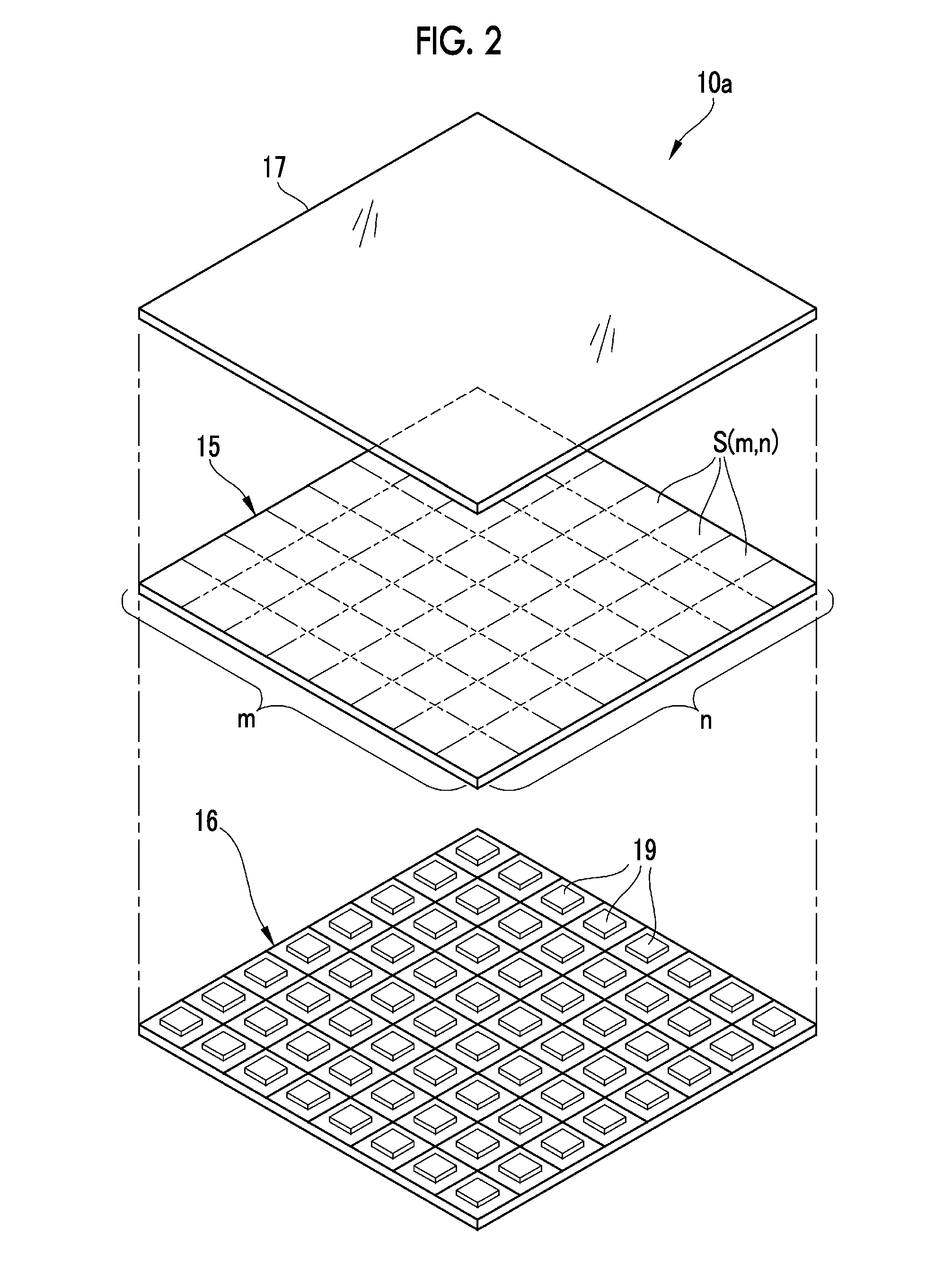
[0059]As shown in FIG. 2, a display section 10a of the liquid crystal display device 10 mainly includes a liquid crystal panel (non-self-luminous display panel) 15, a backlight (light source) 16, and a protection panel 17. In the liquid crystal panel 15, multiple liquid crystal elements are arranged. Thereby, the liqui...

second embodiment

[0124][Liquid Crystal Display Device of Second Embodiment]

[0125]Next, a liquid crystal display device of a second embodiment of the present invention will be described. In the liquid crystal display device 10 of the first embodiment, the Wiener filter is directly used as the inverse filter f−1(x, y). However, in this case, there is a concern about occurrence of disturbance in backlight luminance distribution.

[0126]For example, as shown in the reference numeral 306 of FIG. 16, regarding luminance distribution of the target backlight luminance Bd(x, y), of which the center is bright, it is ideal that it is possible to obtain luminance distribution of such a backlight luminance B(x, y) as indicated by the reference numeral 307. However, in a case where the LED setting value E(m, n) is calculated on the basis of the inverse filter f−1(x, y) which is obtained by directly obtaining a filter coefficient from the Wiener filter, as indicated by the reference numeral 308, luminance distributi...

third embodiment

[0150][Liquid Crystal Display Device of Third Embodiment]

[0151]Next, a liquid crystal display device of a third embodiment of the present invention will be described. The inverse filter processing using the inverse filter f−1(x, y) of the first embodiment is digital filter processing on the real space. However, the Wiener filter obtained through Expression (15) mentioned above is a filter coefficient on the frequency space. Hence, it is necessary to obtain a filter coefficient of the inverse filter f−1(x, y) on the real space through inverse Fourier transform of the Wiener filter which is obtained through Expression (15). The number of samples of the filter coefficient obtained therein is equal to the number of frequency samples obtained when the Wiener filter is calculated.

[0152]FIG. 22 shows an example of the filter coefficient of the inverse filter f−1(x, y) which is obtained through inverse Fourier transform of the Wiener filter in one dimension. In the example of FIG. 22, the n...


PUM


Abstract

On the basis of the image data obtained by the image data acquisition section, a target luminance calculation section calculates a target luminance, which is a target value for the luminance of emitted light for each segment region. An inverse filter acquisition section acquires an inverse filter of a light emission distribution function which represents light emission distribution characteristics of the light source for each segment region. A setting value calculation section calculates a setting value for the luminance of emitted light of the light source for each segment region by performing a convolution operation on the target luminance for each segment region with the inverse filter. On the basis of the setting value for each segment region calculated by the setting value calculation section, a light source control section controls the luminance of emitted light of the light source for each segment region.

Description

CROSS-REFERENCE TO RELATED APPLICATIONS[0001]This application is a Continuation of PCT International Application No. PCT / JP2014 / 077153 filed on Oct. 10, 2014, which claims priority under 35 U.S.C. §119(a) to Japanese Patent Application No. 2013-234117 filed on Nov. 12, 2013. Each of the above applications is hereby expressly incorporated by reference, in their entirety, into the present application.BACKGROUND OF THE INVENTION[0002]1. Field of the Invention[0003]The present invention relates to a display device, which separately controls a luminance of emitted light for each segment region, and a control method for the same.[0004]2. Description of the Related Art[0005]Most portable terminals such as tablet terminals and smartphones, digital cameras, TVs, and various monitors have liquid crystal display devices (display devices). Liquid crystal display devices comprise: a liquid crystal panel in which a light transmittance is adjustable for each pixel; and a backlight (light source) t...

Claims


Application Information

Patent Timeline
Patent Type & Authority Applications(United States)
IPC IPC(8): G09G3/34H04N5/57
CPCG09G3/3426G09G2320/0271G09G2320/0646H04N21/4318G09G2360/16H04N5/57G09G2320/0686
Inventor TAMARU, MASAYA
Owner FUJIFILM CORP
Why Eureka
Try Eureka