Video encoding device, video transcoding device, video encoding method, video transcoding method, and video stream transmission system

a video and transcoding technology, applied in the field of video transcoding devices, video transcoding devices, video transcoding methods, and video stream transmission systems, can solve the problems of large processing load on main display equipment, degraded image quality, and difficulty for users to watch and listen to video

Inactive Publication Date: 2016-08-11
MITSUBISHI ELECTRIC CORP
View PDF5 Cites 7 Cited by
  • Summary
  • Abstract
  • Description
  • Claims
  • Application Information

AI Technical Summary

Benefits of technology

[0025]Because the bitstream generator in accordance with the present invention multiplexes the hint information into the bitstream, the hint information including the motion vector limitation information indicating the range in which a search for a motion vector can be performed, the GOP size limitation information indicating the GOP size which is the number of pictures belonging to the GOP, and the reference configuration specification information indicating a picture to be referred to at the time of decoding each picture belonging to the GOP, there is provided an advantage of being able to generate a bitstream of an entire region which is suitable for efficient generation, with a low operation amount, of a bitstream of a partial region without causing a reduction in the compression efficiency of the bitstream of the entire region.

Problems solved by technology

There is assumed to be a case in which when a user watches and listens to an ultra-high definition video, it becomes difficult for the user to watch and listen to the video even if a fine structure (e.g., character information, a person's face, or the like) in the video exists as information included in the video because the apparent size of display equipment is too small as compared with the number of pixels of the video.
However, a problem with the case of using the method 1 is that because it is necessary to encode the decoded image of the partial region again, the processing load on the main display equipment becomes large and the image quality degrades due to the re-encoding.
However, because the extraction of encoded data and coding parameters is carried out on a per tile basis in the case of using the method 2, a partial region bitstream including many regions unnecessary for display is generated and hence this generating process is inefficient when the partial region specified by the user extends across a plurality of tiles and when the tile size is larger than the size of the partial region.
Because the number of parts at each of which the reference is cut off increases as the tile size is reduced in order to improve the efficiency of generation of a partial region bitstream, there arises a problem that the compression efficiency of the entire region bitstream degrades.

Method used


Image

  • Video encoding device, video transcoding device, video encoding method, video transcoding method, and video stream transmission system
  • Video encoding device, video transcoding device, video encoding method, video transcoding method, and video stream transmission system
  • Video encoding device, video transcoding device, video encoding method, video transcoding method, and video stream transmission system

Examples


embodiment 1

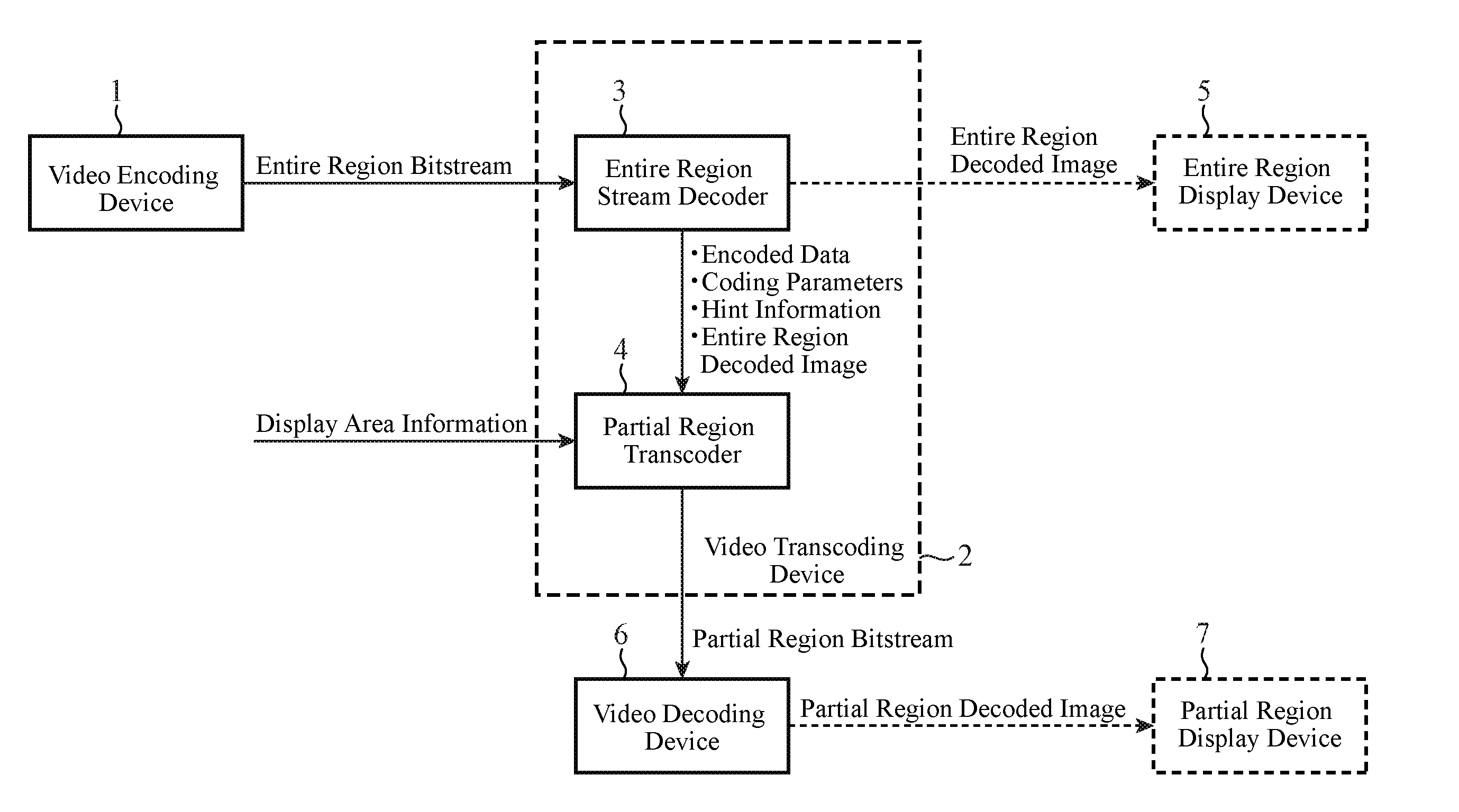
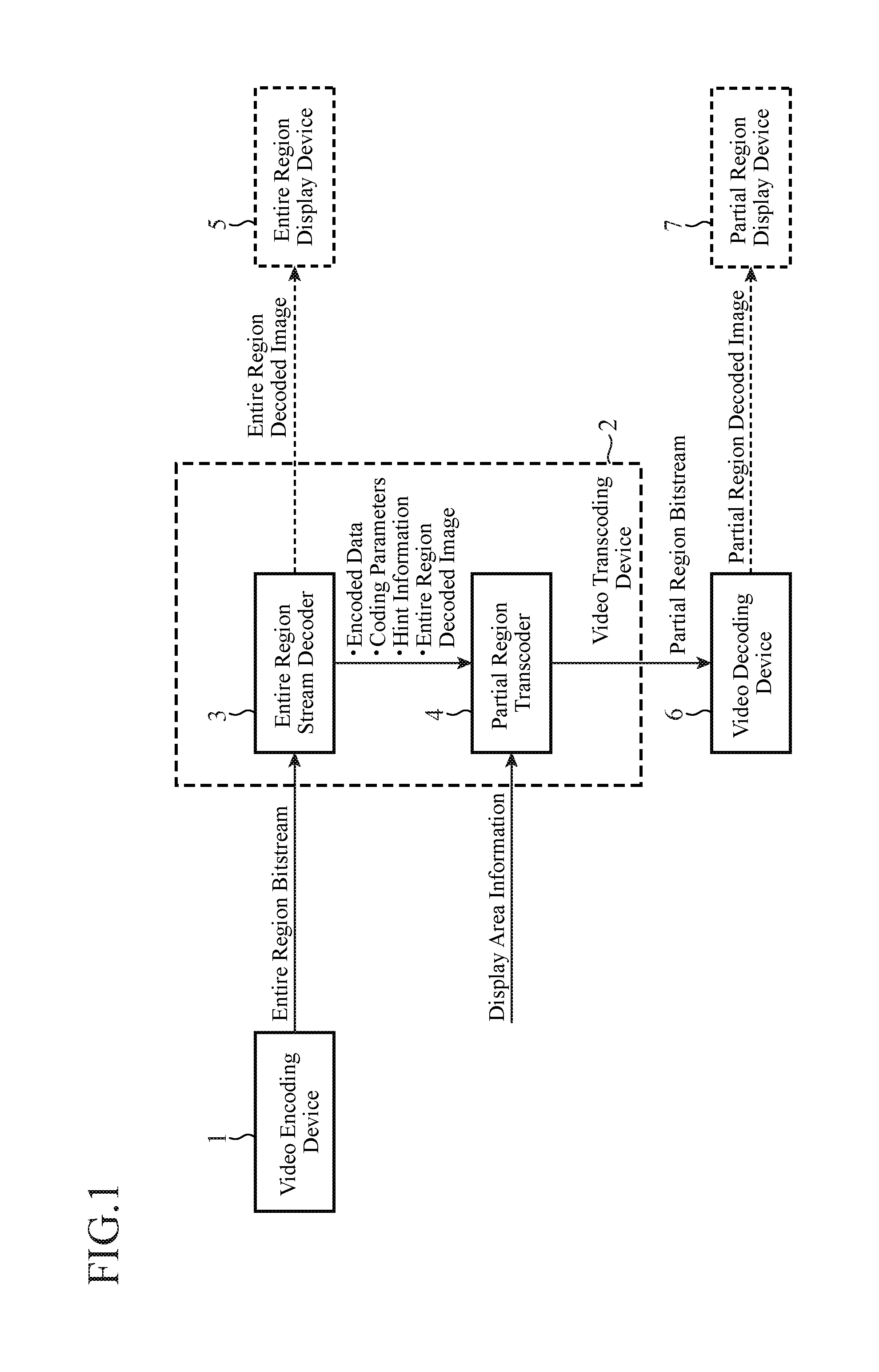
[0042]In this Embodiment 1, an explanation will be made as to a video encoding device that, by imposing a limitation on a maximum of a motion vector used at the time of performing an inter frame prediction, and a limitation on the number of frames between random access points, carries out encoding in such a way that the propagation range of pixel value information between random access points falls within certain limits, to generate a bitstream of an entire region, and that also multiplexes information indicating a limit value of the maximum of motion vectors, information indicating a limit value of the number of frames between random access points, and so on, as hint information, into the entire region bitstream.

[0043]Further, an explanation will be made as to a video transcoding device that decodes the encoded data of the entire region from the entire region bitstream generated by the above-mentioned video encoding device and also refers to the hint information multiplexed into th...

embodiment 2

[0266]In this Embodiment 2, an example in which a video encoding device and a video transcoding device as shown in above-mentioned Embodiment 1 are applied to a system different from that in accordance with above-mentioned Embodiment 1 will be explained.

[0267]FIG. 11 is a block diagram showing a system to which a video encoding device and a video transcoding device in accordance with Embodiment 2 of the present invention are applied.

[0268]Referring to FIG. 11, the video encoding device 51 has the same functions as those of the video encoding device 1 shown in FIG. 1. The video encoding device 51 outputs an entire region stream generated thereby to either a video distribution device 53 or a storage 52.

[0269]The video distribution device 53 is configured with an entire region stream decoder 54, a partial region transcoder 55, and a distribution controller 56, and has a function of generating partial region streams on the basis of the entire region bitstream generated by the video enco...

embodiment 3

[0283]In this Embodiment 3, a video stream transmission system for employing the video encoding device and the video transcoding device which are shown in any of above-mentioned Embodiments 1 and 2 more efficiently will be explained.

[0284]In this Embodiment 3, a state in which an entire region image is partitioned into subpictures, such as slices or tiles, is assumed.

[0285]FIG. 12 is an explanatory drawing showing an example in which an entire region image is partitioned into six subpictures (Sub-pic).

[0286]FIG. 13 is a block diagram showing the video stream transmission system in accordance with Embodiment 3 of the present invention. In FIG. 13, because the same reference numerals as those shown in FIG. 1 denote the same components or like components, the explanation of the components will be omitted hereafter.

[0287]A video encoding device 1 is the same as the video encoding device 1 shown in above-mentioned Embodiment 1 (or the video encoding device 51 shown in above-mentioned Emb...


PUM


Abstract

A variable length encoder 23 multiplexes hint information into an entire region bitstream, the hint information including motion vector limitation information indicating a maximum range in which a search for a motion vector can be performed, GOP size limitation information indicating a GOP size which is the number of pictures belonging to a GOP, and reference configuration specification information indicating a picture to be referred to at the time of decoding each picture belonging to the GOP. As a result, a bitstream of the entire region which is suitable for efficient generation, with a low operation amount, of a bitstream of a partial region can be generated without causing a reduction in the compression efficiency of the bitstream of the entire region.

Description

FIELD OF THE INVENTION[0001]The present invention relates to an image encoding device for and an image encoding method of compression-encoding an image to generate encoded data, a video transcoding device for and a video transcoding method of generating other encoded data having a different feature from the encoded data generated by the image encoding device, and a video stream transmission system for transmitting and receiving the encoded data generated by the image encoding device.BACKGROUND OF THE INVENTION[0002]As imaging equipment, display equipment, compression encoding techniques, transmission techniques, and so on progress, services for distribution of UHD (Ultra-High Definition) videos having definition (e.g., definition such as 4K or 8K) exceeding HD (High Definition) have been studied.[0003]Because an ultra-high definition video has a huge amount of video information, an ultra-high definition video is compressed typically by using a video encoding technique at the time of...

Claims


Application Information

Patent Timeline
Patent Type & Authority Applications(United States)
IPC IPC(8): H04N19/463H04N19/593H04N19/52H04N19/573H04N19/91H04N19/40
CPCH04N21/4728H04N19/573H04N19/40H04N21/2343H04N21/236H04N19/196H04N19/61H04N19/107H04N19/114H04N19/174H04N19/167H04N19/593H04N19/91H04N19/463H04N19/52H04N19/46H04N19/105H04N19/55H04N19/57H04N19/58
Inventor HATTORI, RYOJIMORIYA, YOSHIMIMINEZAWA, AKIRAMIYAZAWA, KAZUYUKISEKIGUCHI, SHUNICHI
Owner MITSUBISHI ELECTRIC CORP
Why Eureka
Try Eureka