
Absorption tower having absorption separator

a technology of absorption separator and absorption tower, which is applied in the direction of separation of dispersed particles, transportation and packaging, and process separation, etc., can solve the problems of difficult to control the level of the absorbent liquid precisely, difficult to control difficulty in regulating the level of the absorbent liquid, so as to prevent efficiency deterioration, the effect of fast linear velocity of the object gas and level control of the rich absorbent liquid in the absorbent liquid

Active Publication Date: 2016-08-18
HYUNDAI MOTOR CO LTD +1
View PDF2 Cites 0 Cited by
  • Summary
  • Abstract
  • Description
  • Claims
  • Application Information

AI Technical Summary

Benefits of technology

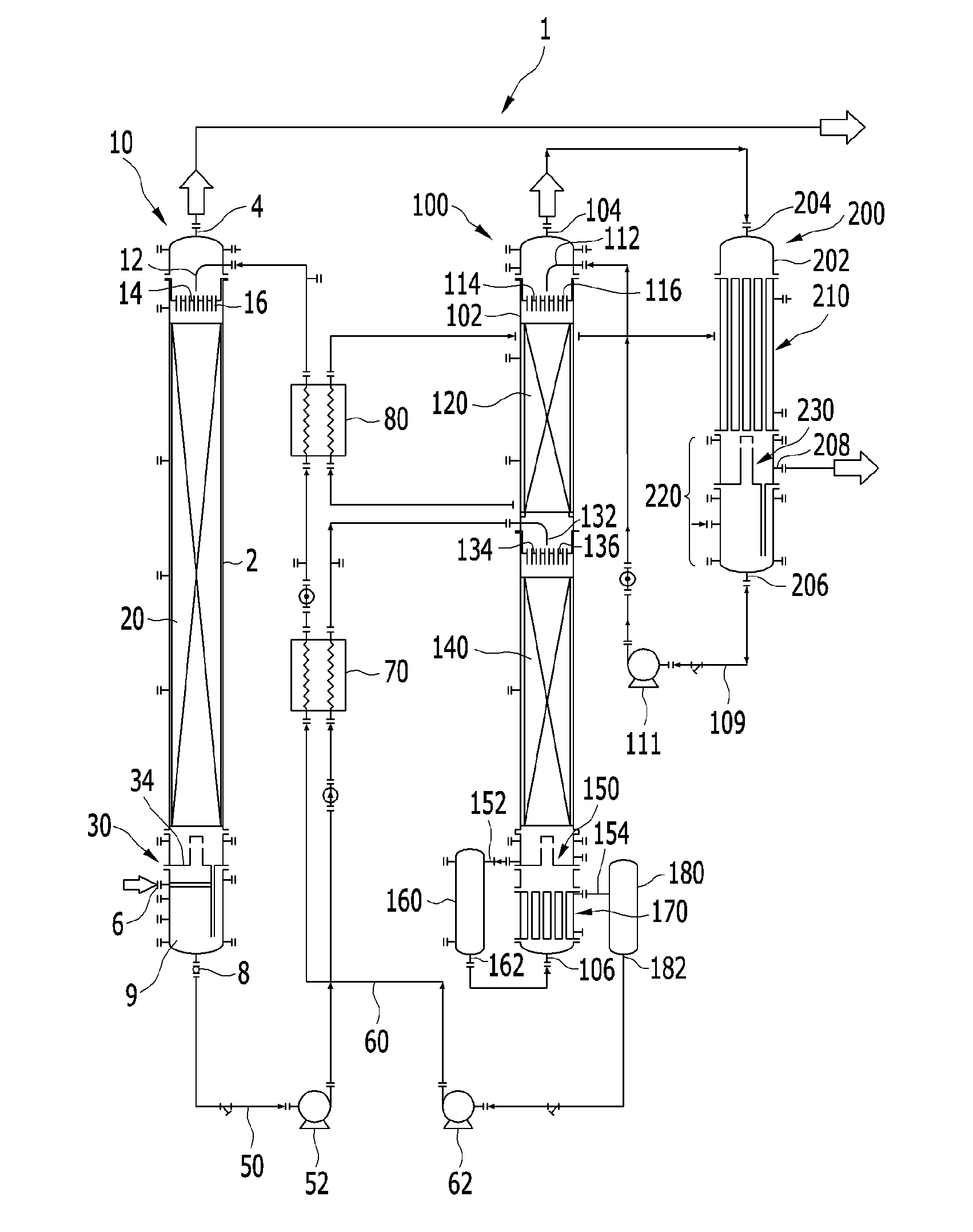
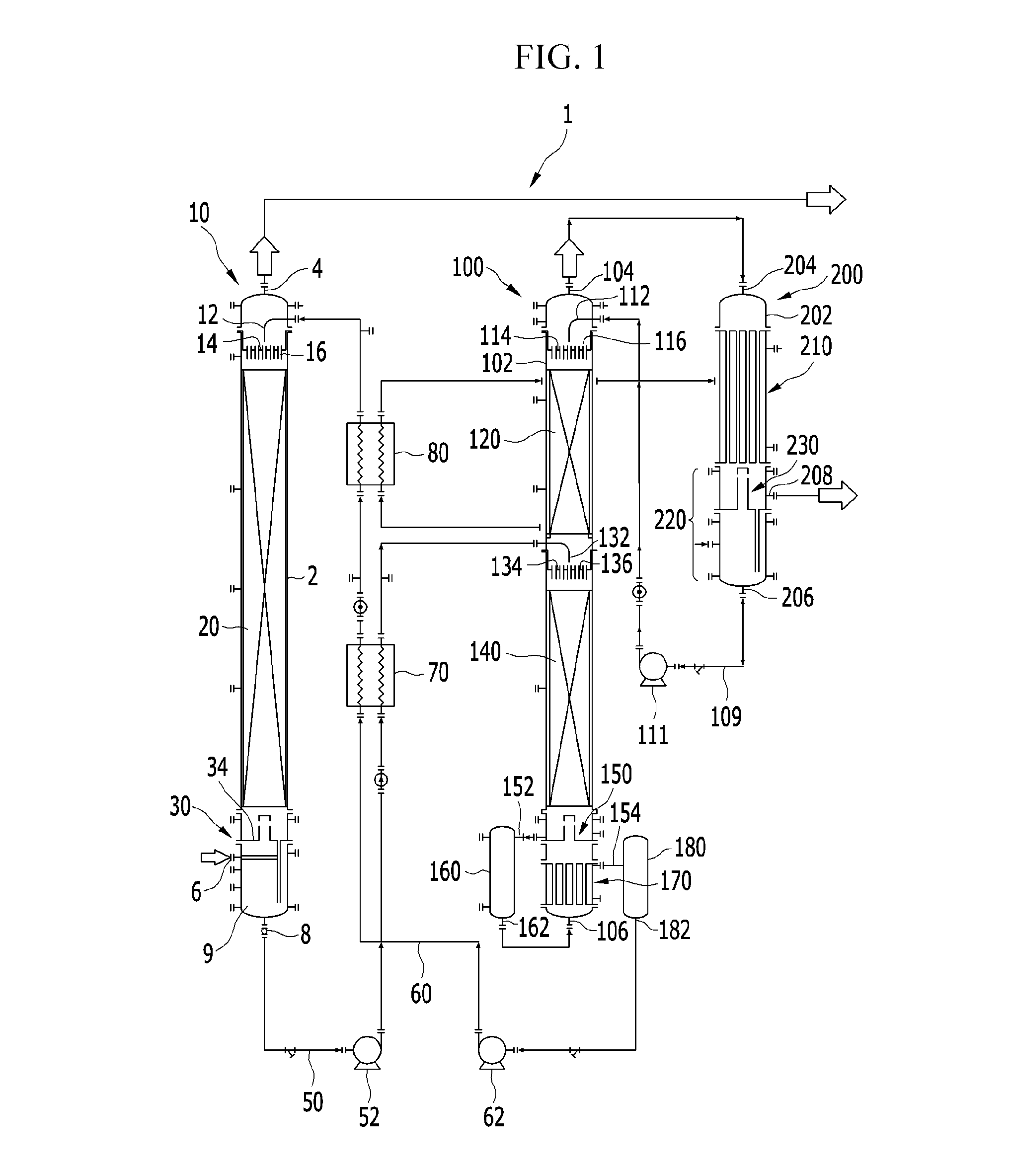
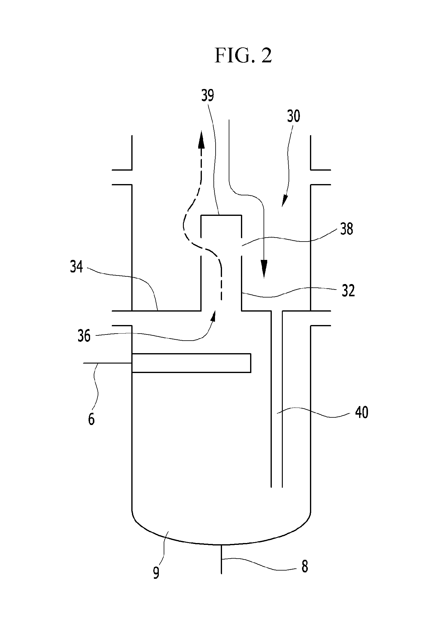
The present invention provides an absorption tower with an absorption separator that separates a supply path of rich absorbent liquid from a path of object gas, which prevents changes in the composition of the rich absorbent liquid due to the high linear velocity of the object gas and deterioration of efficiency. This results in improved level control of the absorbent liquid and prevention of composition change.

Problems solved by technology

However, it is very difficult to control the conventional gas collecting plant when abnormal phenomena occur due to fast linear velocity of gas at a lower portion of the absorption tower and absorbent liquid drop.
Therefore, it is difficult to control a level of the absorbent liquid precisely.
According to the thermocyphon reboiler, a level of the absorbent liquid is hard to be controlled due to boiling.
In addition, since there is no wall in the boiler, the mixed liquid remains in the reboiler in a very short time.
Therefore, less energy is supplied to the mixed liquid and gas separation efficiency for regeneration is very low.
Therefore, if bubbles occur due to heating, the mixed liquid cannot reach the heater or the heat-exchanger due to the bubbles.
If this condition continues, the level of the mixed liquid in the regeneration tower is raised too high that the absorption tower and the regeneration tower cannot work.
As a result, a volume of the gas collecting plant becomes large, and a large space is necessary to mount the gas collecting plant.
In addition, since the reflux apparatus and the condenser are separated, a large amount of heat loss occurs between the reflux apparatus and the condenser.

Method used


Image

  • Absorption tower having absorption separator
  • Absorption tower having absorption separator
  • Absorption tower having absorption separator

Examples


Embodiment Construction

[0034]“Rich absorbent liquid” in this specification and claims means absorbent liquid containing large amount of gas that is removing object or absorbent liquid after absorbing the gas and before regenerating the gas.

[0035]“Lean absorbent liquid” in this specification and claims means absorbent liquid containing little amount of gas that is removing object or absorbent liquid from which gas is separated.

[0036]“Regeneration” in this specification and claims means separation of gas from absorbent liquid.

[0037]“Regeneration gas” in this specification and claims means gas separated from absorbent liquid.

[0038]“Object gas” in this specification and claims means gas that is regeneration object, i.e., gas before regeneration.

[0039]“Target gas” in this specification and claims means gas that will be separated from the object gas and will be collected.

[0040]“Treated gas” in this specification and claims means gas remaining after the object gas is dissolved in absorbent liquid.

[0041]“Evaporat...


PUM

PropertyMeasurementUnit
shapeaaaaaaaaaa
heightaaaaaaaaaa
structureaaaaaaaaaa

Abstract

A lean absorbent liquid supplier, disposed inside at an upper portion in the absorption tower housing, supplies a lean absorbent liquid into the housing. An absorption tower rectifier, disposed under the lean absorbent liquid supplier in the absorption tower housing, rectifies flow of the lean absorbent liquid supplied downwardly in the absorption tower housing, and dissolves an object gas in the lean absorbent liquid to generate a rich absorbent liquid. An absorbent liquid chamber, disposed below the absorption tower rectifier in the absorption tower housing temporarily stores the rich absorbent liquid therein. An absorption separator is disposed between the absorption tower rectifier and the absorbent liquid chamber in the absorption tower housing. The object gas is supplied to the absorbent liquid chamber.

Description

CROSS-REFERENCE TO RELATED APPLICATION[0001]This application claims the benefit of priority to Korean Patent Application No. 10-2015-0023458 filed in the Korean Intellectual Property Office on Feb. 16, 2015, the entire content of which is incorporated herein by reference.TECHNICAL FIELD[0002]The present disclosure relates to an absorption tower with an absorption separator that is commonly applicable to gas-liquid separating processes. More particularly, the present disclosure relates to an absorption tower with an absorption separator that facilitates level control of rich absorbent liquid in an absorbent liquid chamber and prevents change of composition in absorbent liquid.BACKGROUND[0003]As global warming and air pollution become more severe, techniques for suppressing carbon dioxide emission into the atmosphere have been aggressively developed. Particularly, a method of efficiently trapping carbon dioxide emitted from thermoelectric power plants or boiler equipment has been unde...

Claims


Application Information

Patent Timeline
Patent Type & Authority Applications(United States)
IPC IPC(8): B01D53/18B01F15/06B01F3/04
CPCB01D53/18B01F3/04078B01F2015/062B01F3/04496B01F15/06B01F3/04468B01D53/1425B01D53/1475B01D2258/0283Y02C20/40B01D53/14B01F23/214B01F23/2321B01F35/712
Inventor BAE, SHIN-TAENAM, SUNGCHANPARK, SUNGYEOULYOON, YEOIL
Owner HYUNDAI MOTOR CO LTD
Learn More