
Method and apparatus for early detection of kicks

a technology for early detection and kicks, applied in earth-moving drilling, surveying, wellbore/well accessories, etc., can solve the problems of gas influx into the wellbore or loss of drilling mud into the reservoir, and the condition indicating a kick is typically not readily detectable by the human ey

Active Publication Date: 2016-08-18
BOARD OF RGT THE UNIV OF TEXAS SYST
View PDF3 Cites 65 Cited by
  • Summary
  • Abstract
  • Description
  • Claims
  • Application Information

AI Technical Summary

Benefits of technology

The disclosed technique presents a well monitoring system that can detect kicks in a well. The system includes a well, sensors to measure various well conditions, a computing apparatus with a processor and storage. The computing apparatus uses a physics-based model to estimate the well condition based on the sensor data and a machine learning algorithm to detect kicks and determine its probability. This technique can improve well safety and prevent damage to the environment.

Problems solved by technology

The efforts of the oil and gas industry to discover and bring into production new or additional hydrocarbon deposits has led to ever more sophisticated and demanding technical environments.
This sophistication and demand is reflected in the costs of the endeavor.
Drilling operations and unanticipated high pressure gas pockets in porous rock formations can lead to pressure imbalances between wellbore fluids and reservoir fluids, causing gas influx into the wellbore or loss of drilling mud into the reservoir.
One issue in kick detection is that the conditions indicating that a kick has occurred are typically not readily detectable by the human eye.
A fair portion of this fact is that many of the conditions used to detect or predict a kick are downhole, and so are not readily discernible directly to the human eye.
However, even with automated monitoring systems, many techniques for detecting and managing kicks suffer from a number of drawbacks.
It is not uncommon for them to rely on lagging rather than leading indicators, which can delay an otherwise timely response.
They are also subject unpredictable human error.

Method used


Image

  • Method and apparatus for early detection of kicks
  • Method and apparatus for early detection of kicks
  • Method and apparatus for early detection of kicks

Examples


Embodiment Construction

[0022]Illustrative embodiments of the subject matter claimed below will now be disclosed. In the interest of clarity, not all features of an actual implementation are described in this specification. It will be appreciated that in the development of any such actual embodiment, numerous implementation-specific decisions must be made to achieve the developers' specific goals, such as compliance with system-related and business-related constraints, which will vary from one implementation to another. Moreover, it will be appreciated that such a development effort, even if complex and time-consuming, would be a routine undertaking for those of ordinary skill in the art having the benefit of this disclosure.

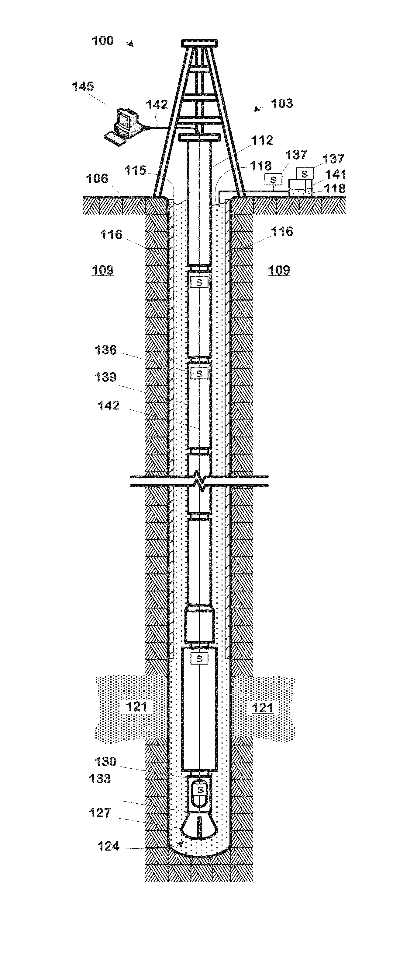
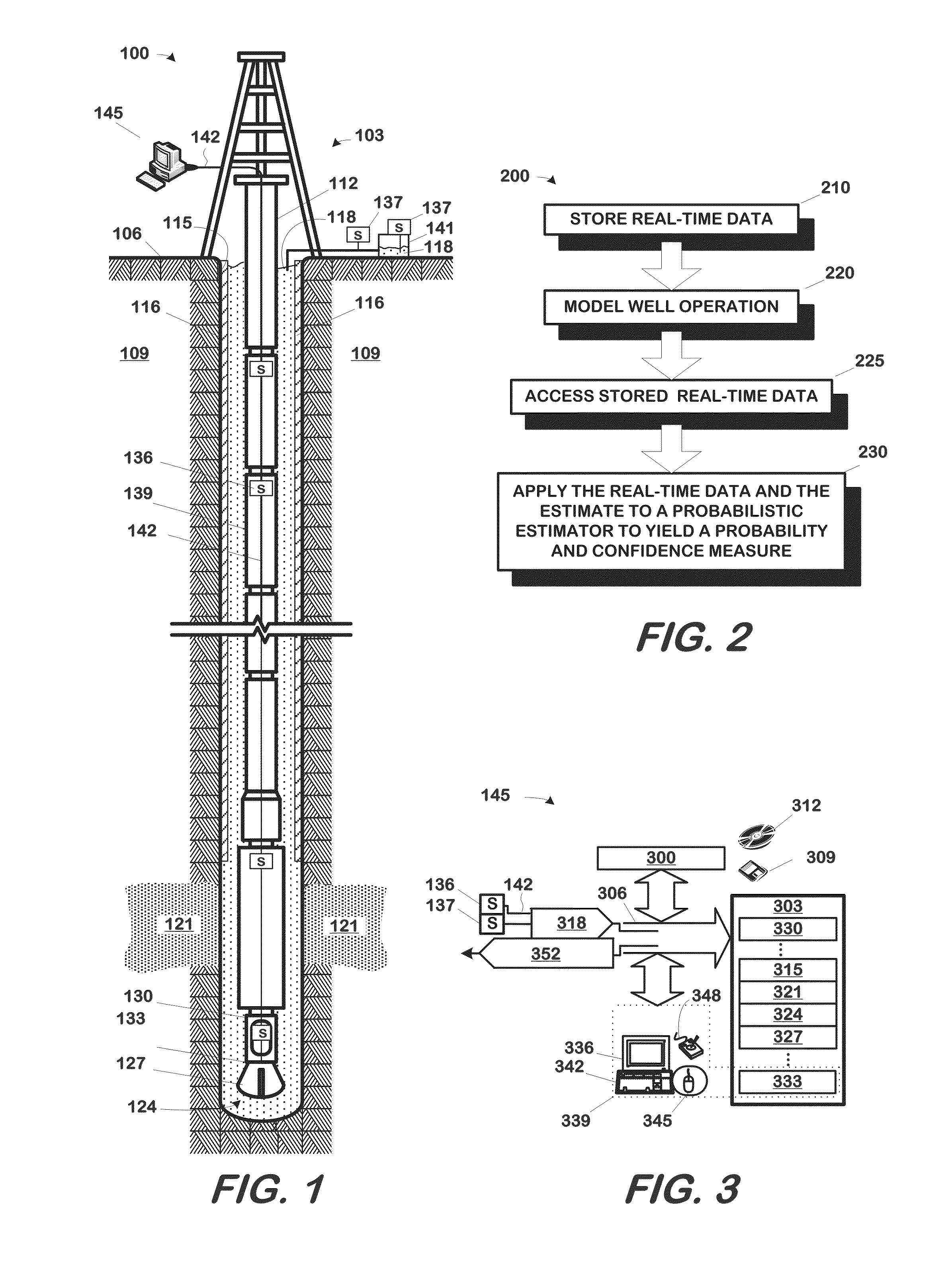
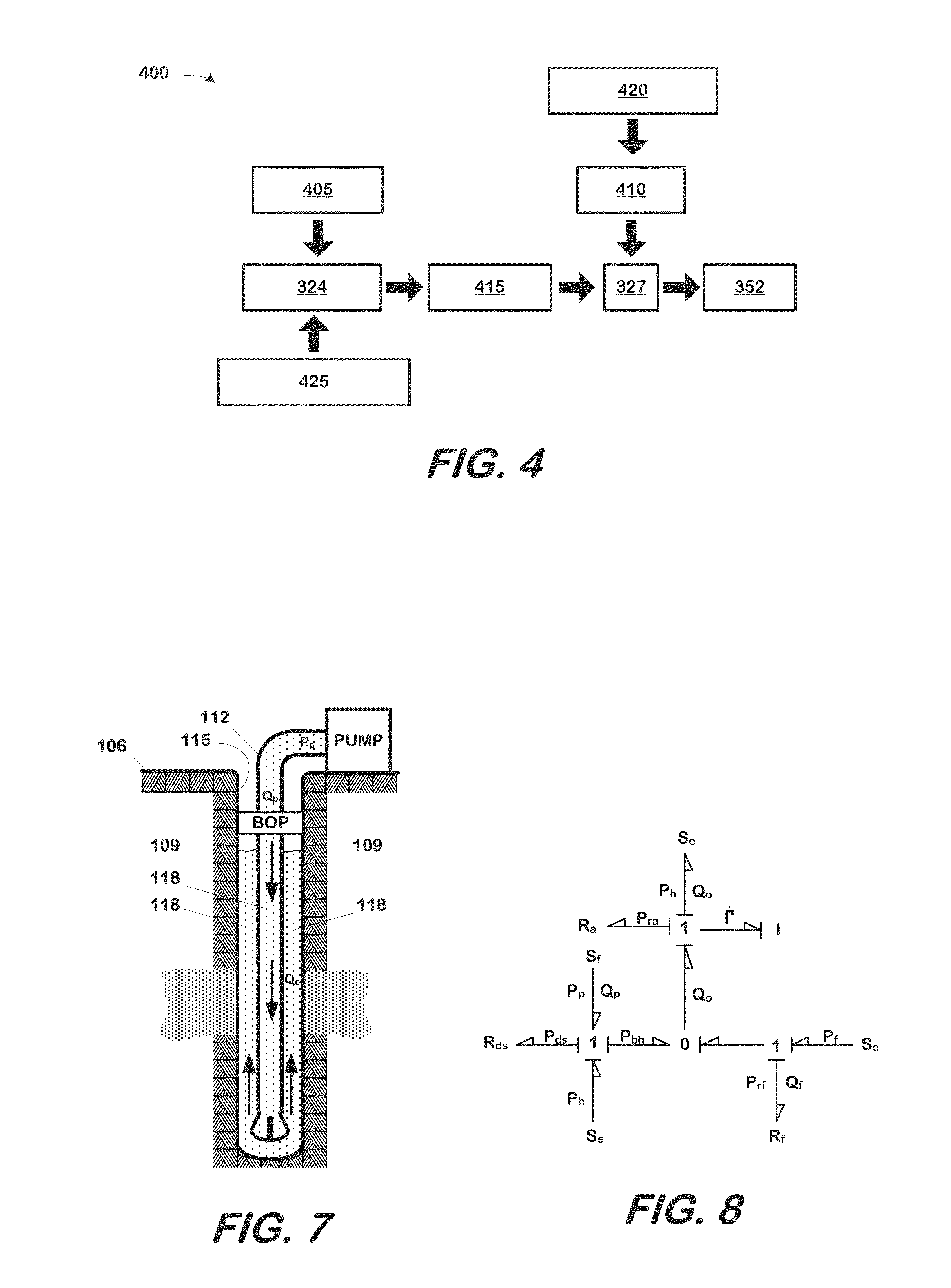
[0023]The technique disclosed herein and claimed below employs a cyber-physical approach to the detection, monitoring, and managing of kick in wells. For present purposes, a “cyber-physical” technique is one in which a model of the well system for the well is coupled to the well system...


PUM


Abstract

A well monitoring system particularly useful in detecting kicks in the well includes a well, a well system, and a computing apparatus. The well defines a wellbore and the well system includes at least one sensor measuring at least one well condition. The computing apparatus hosts a well monitoring software component that performs a method to detect a kick in a well. The method includes: storing a set of real-time data from a measurement of a well condition by the sensor, the measurements being correlative to an unplanned fluid influx into the well; modeling the operation of the well with a physics-based, state space model of the well system to obtain an estimate of the well condition; and applying the real-time data set and the estimate to a probabilistic estimator to yield a probability of an occurrence of a kick and a confidence measure for the probability.

Description

CROSS-REFERENCE TO RELATED APPLICATIONS[0001]This application claims the priority of U.S. Provisional Application Ser. No. 62 / 117,061, filed Feb. 17, 2015, and hereby incorporates that application by reference for all purposes as if set forth verbatim herein.STATEMENT REGARDING FEDERALLY SPONSORED RESEARCH OR DEVELOPMENT[0002]Not applicable.BACKGROUND[0003]This section of this document introduces various information that may be related to or provide context for some aspects of the technique described herein and / or claimed below. It provides background information to facilitate a better understanding of that which is disclosed herein. This is therefore a discussion of “related” art. That such art is related in no way implies that it is also “prior” art. The discussion in this section is to be read in this light, and not as admissions of prior art.[0004]The efforts of the oil and gas industry to discover and bring into production new or additional hydrocarbon deposits has led to ever ...

Claims


Application Information

Patent Timeline
IPC IPC(8): E21B47/10
CPCE21B47/10
Inventor BEAMAN, JR., JOSEPH J.FISH, SCOTTFOTI, DAVID A.WINTERS, WARREN J.
Owner BOARD OF RGT THE UNIV OF TEXAS SYST
Learn More