Battery pack

a battery pack and battery technology, applied in the field of batteries, can solve the problems of uneven cooling draft provided by the ventilation mechanism, adverse manner, and battery cells that cannot be charged as quickly, and achieve the effects of improving cooling efficiency, reducing the rattling of battery cells in the interior of the case, and increasing the cooling efficiency of one or more battery cells

Active Publication Date: 2016-08-18
MAKITA CORP
View PDF4 Cites 27 Cited by
  • Summary
  • Abstract
  • Description
  • Claims
  • Application Information

AI Technical Summary

Benefits of technology

[0006]In view of these circumstances, one non-limiting object of the present teachings is to provide a battery pack that is mountable on a tool main body of a power tool and that is designed to improve the evenness of the cooling of all of the battery cells during a charging operation. For example, in some embodiments of the present teachings, the battery pack may be designed such that cooling air (one or more cooling drafts) blows against (contacts) all of the battery cells, even if the battery cells are disposed in parallel in a longitudinal arrangement in the interior of the case. Such a design has the advantageous effect of reducing cooling unevenness among the battery cells, which permits higher (larger) charging currents to be applied to the battery cells during the charging operation. Consequently, the charging time can be safely decreased because there is a reduced risk of damage to the battery cells caused by excessive temperatures.
[0018]In a tenth aspect of the present teachings, the first ventilation hole is defined on the upstream side of the drafts that flow into the longitudinal-direction passageways within the case. The second ventilation holes are defined on a downstream side of the (branched) drafts that flow in the longitudinal-direction passageways within the case. In such an embodiment, the longitudinal-direction passageways can be defined without impeding the flow of the draft(s). As a result, the cooling efficiency of the battery cells can be better achieved.

Problems solved by technology

However, in such a longitudinal arrangement, the cooling draft supplied by the ventilation mechanism may be unevenly guided to (contact) the battery cells disposed in parallel.
Thus, uneven cooling of the battery cells could result in an adverse manner.
Such cooling unevenness means that the battery cells may not be charged as quickly as may be permitted by the battery chemistry (i.e. if the cooling effectiveness / evenness were better), because one or more of the battery cells may reach damagingly high temperatures during the charging due to the high current applied to the battery cells and the insufficient cooling of such battery cell(s).

Method used


Image

  • Battery pack
  • Battery pack
  • Battery pack

Examples


first embodiment

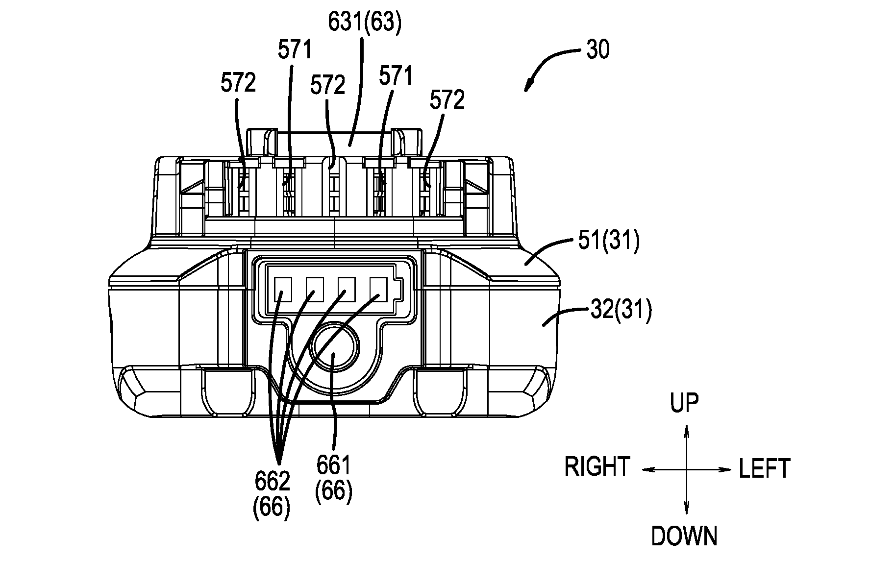
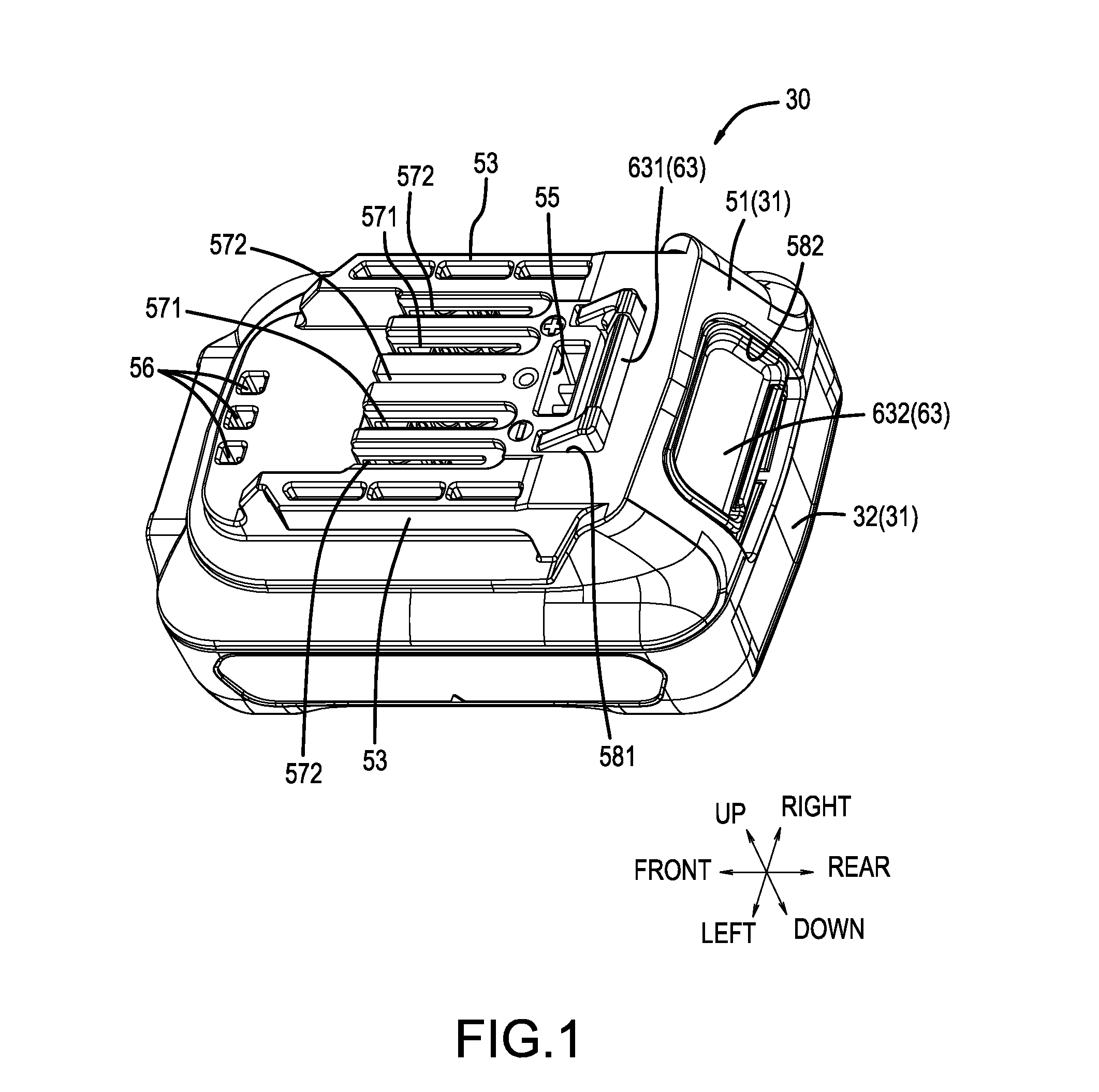
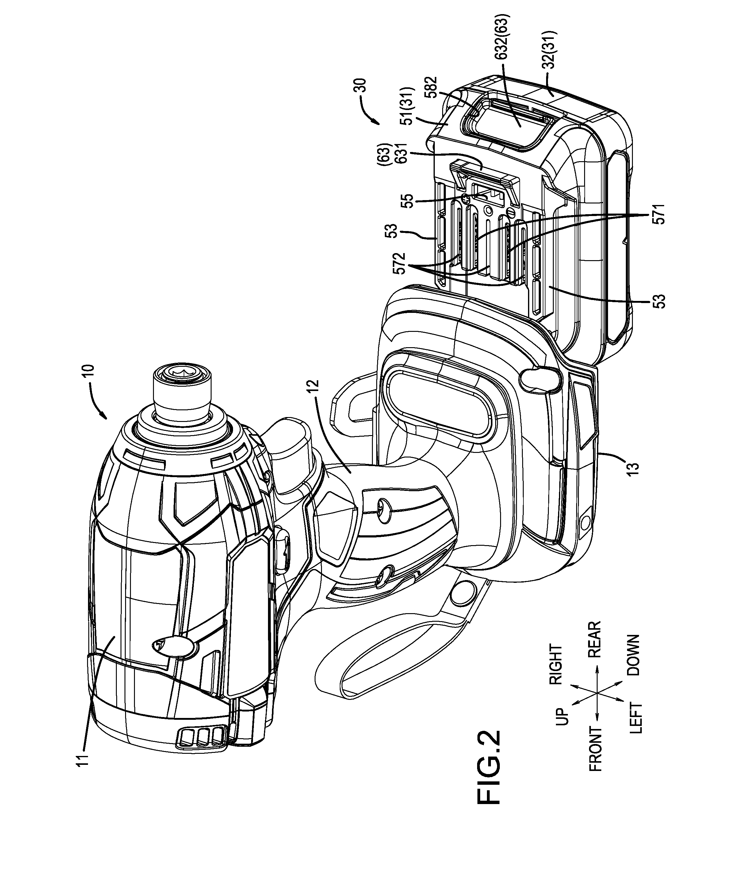
[0043]A first embodiment for implementing a representative, non-limiting battery pack 30 according to the present teachings is explained below with reference to FIG. 1 to FIG. 19. Referring first to FIGS. 1-4, the battery pack 30 is designed to serve as a power supply of a power tool and is capable of being mounted on the tool main body 10. In the present embodiment, the cordless power tool is an impact driver, although the present battery packs may be used with a wide variety of cordless power tools, as will be described below. The battery pack 30 is mounted and dismounted by being slid relative to a battery-mounting part 13 of the tool main body 10.

[0044]Generally speaking, the tool main body 10 comprises, in order from above, a drive part 11, a grip part 12, and the battery-mounting part 13. The battery-mounting part 13 is provided with female rails 14 for sliding engagement with the battery pack 30. A positive terminal 15, a negative terminal 16, and a communication terminal 17 ...

second embodiment

[0095]Next, a second embodiment for implementing the battery pack according to the present teachings will be explained, with reference to FIG. 20 to FIG. 24. The battery pack 30A of the second embodiment principally differs from the battery pack 30 of the above-described first embodiment with regard to the number of battery cells 72.

[0096]Specifically, in the battery pack 30 according to the first embodiment, three of the battery cells 72 are longitudinally disposed in parallel. In contrast, in the battery pack 30A according to the second embodiment, two levels, in the up-down direction, of battery cells 72a, 72b are provided, each level comprising three of the battery cells longitudinally disposed in parallel. Therefore, the battery pack 30A according to the second embodiment contains a total of six of the battery cells 72a, 72b, in which two levels of three battery cells 72 are stacked in a direction (the up-down direction) orthogonal to the direction that the battery cells 72 are...


PUM

PropertyMeasurementUnit
angleaaaaaaaaaa
voltageaaaaaaaaaa
volumeaaaaaaaaaa

Abstract

As a cooling draft flows from a rear side to a front side of battery cells (72) inside a battery pack (30), it is divided into two cooling drafts (F1, F2) in a left-right direction, which is the direction that the battery cells (72) are disposed in parallel, and those two cooling drafts respectively flow through a plurality of passageways that longitudinally extend along the battery cells (72). More particularly, a second battery cell (722) is cooled by the cooling draft flowing in a second ventilation-path volume (Q2) before a first battery cell (721) and a third battery cell (723) are cooled by cooling drafts respectively flowing in a first ventilation-path volume (Q1) and a third ventilation-path volume (Q3), which are longer than the second ventilation-path volume (Q2).

Description

CROSS-REFERENCE[0001]This application claims priority to Japanese patent application serial number 2015-026526, filed on Feb. 13, 2015, the content of which are incorporated herein by reference in its entirety.TECHNICAL FIELD[0002]The present invention generally relates to a battery pack that serves as a power supply of a power tool and is mountable on a tool main body of the power tool.BACKGROUND ART[0003]Known power tools have been configured such that a battery pack, which constitutes a drive-power supply of a tool main body, is detachable. The battery pack comprises a case (housing), which constitutes an outer shell, and a battery main body, which is installed in an interior of the case. The battery main body comprises a plurality of rechargeable battery cells. The battery cells that constitute such a battery main body are lined up and disposed so as to minimize the required space in the interior of the case. Specifically, the battery cells are disposed in parallel and the longi...

Claims


Application Information

Patent Timeline
Patent Type & Authority Applications(United States)
IPC IPC(8): H01M10/6566H01M10/6235H01M10/643H01M10/613
CPCH01M10/6566H01M10/613H01M10/6235H01M10/6563H01M2220/30H01M2/1055H01M10/643H01M50/20H01M50/213Y02E60/10
Inventor KONDO, EIJI
Owner MAKITA CORP
Why Eureka
Try Eureka