Planter Exhaust Air Removing Apparatus and Method of Use Thereof

a technology of planter and exhaust air, which is applied in the direction of separation process, single grain seeder, dispersed particle separation, etc., can solve the problems of unsuitably cleaned untreated seeds, unfavorable treatment of untreated seeds, and generating dust and debris, so as to reduce the amount of material requiring disposal, reduce the amount of airflow, and reduce the effect of airflow

Active Publication Date: 2016-08-25
SYNGENTA PARTICIPATIONS AG
View PDF6 Cites 11 Cited by
  • Summary
  • Abstract
  • Description
  • Claims
  • Application Information

AI Technical Summary

Benefits of technology

[0037]Because an advantage of the present invention lies in its ability to be configured without power or energy inputs, passive filters are preferred. However, all suitable equipment and devices for removing fine particles from air flow are encompassed in the invention.
[0038]Paper, fiberglass, fabric such as cotton, and foam such as oil-wetted foam are all examples of materials suitable for a filter element. Electrostatic or high-efficiency particulate air filters (HEPA filters) are widely available, however they may be less preferred since they may not be especially efficient at handling the volume of particles and particle sizes expected under some drilling conditions. Preferred materials and sizes will accommodate the expected capacity with minimal restriction to airflow.
[0039]In a preferred embodiment the filter unit comprises an outer housing to shield the actual filtering material from wind, rain and the like, with an inner portion configured to receive a disposable air filter. For example, a fine dust pocket filter can be placed in the housing and used until the filter contains sufficient dust to start decreasing airflow, at which time it can be removed and disposed of appropriately and a fresh filter inserted in the housing.
[0040]Particularly when drilling treated seed, disposable filters may be preferred. They will be expected to capture some amount of agrochemical waste which may need to be disposed of in a specific manner. A reusable filter which must be washed or cleaned may

Problems solved by technology

For various reasons the seed treatment can fail to form a coherent layer which remains intact through processing, storage, transport and drilling.
Untreated seeds which have not been suitably cleaned generate dust and debris which is carried in the exhaust air.
Likewise waste is present in the exhaust air from treated seeds, whether due to a less than optimal seed treatment or simply because of abrasion during transport, storage

Method used


Image

  • Planter Exhaust Air Removing Apparatus and Method of Use Thereof
  • Planter Exhaust Air Removing Apparatus and Method of Use Thereof
  • Planter Exhaust Air Removing Apparatus and Method of Use Thereof

Examples


example 1

Evaluation of a First Embodiment

[0059]An experiment was conducted to evaluate the performance of an embodiment of the particle removing apparatus of the invention. 140 kg of maize seeds were treated using a WN 5 rotostat treater (Willy Niklas GmbH Apparatebau, Germany) with a conventional seed treatment product (CRUISER insecticide, Syngenta Crop Protection AG, Switzerland; MAXIM XL fungicide, Syngenta Crop Protection AG; SEPIRET 9290 pigment, Becker Underwood, France) according to standard rates and procedures. After drying the seeds were placed in a vacuum planter (MONOSEM 8 rows, MONOSEM, France) and drilled in a field at standard speed using standard techniques.

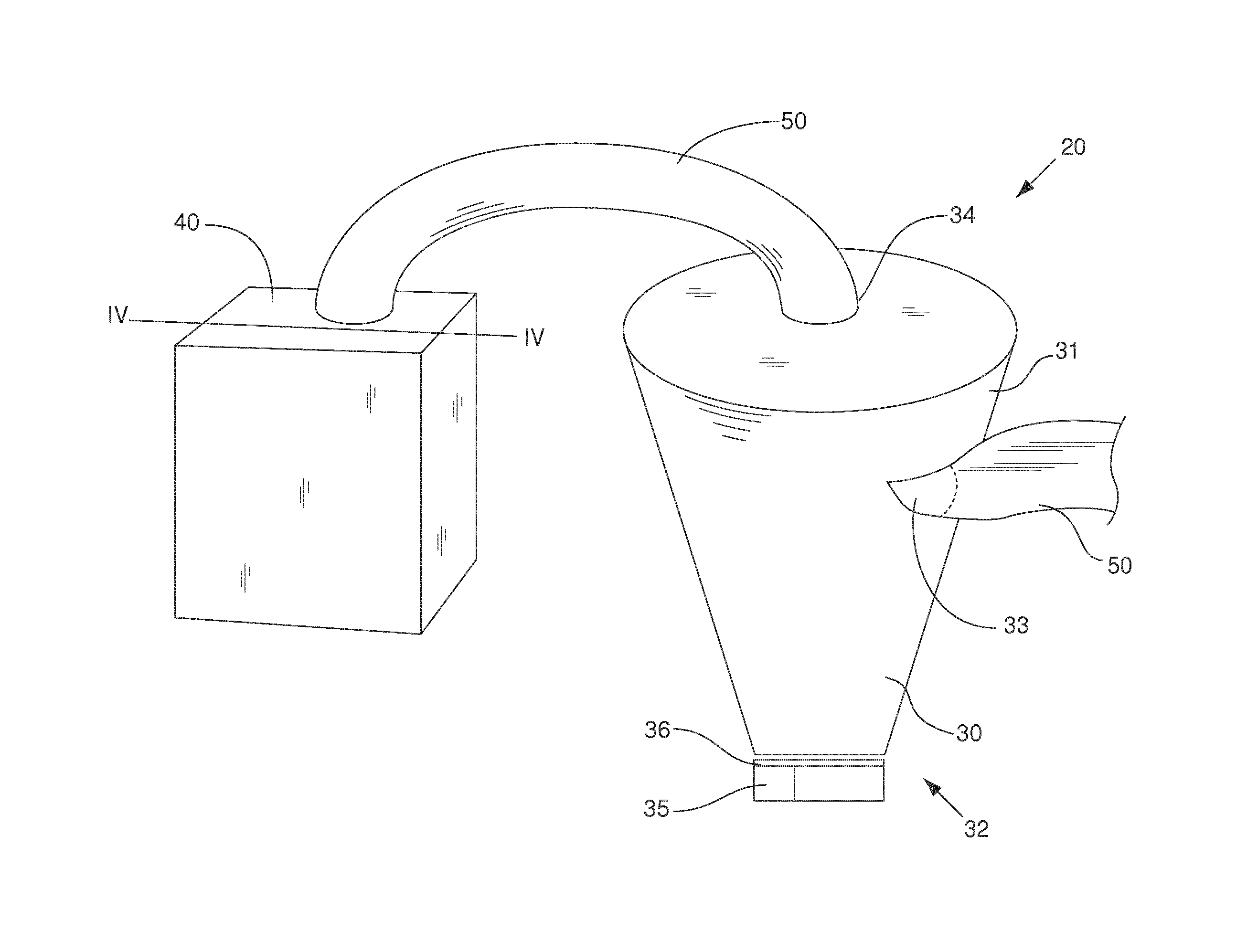
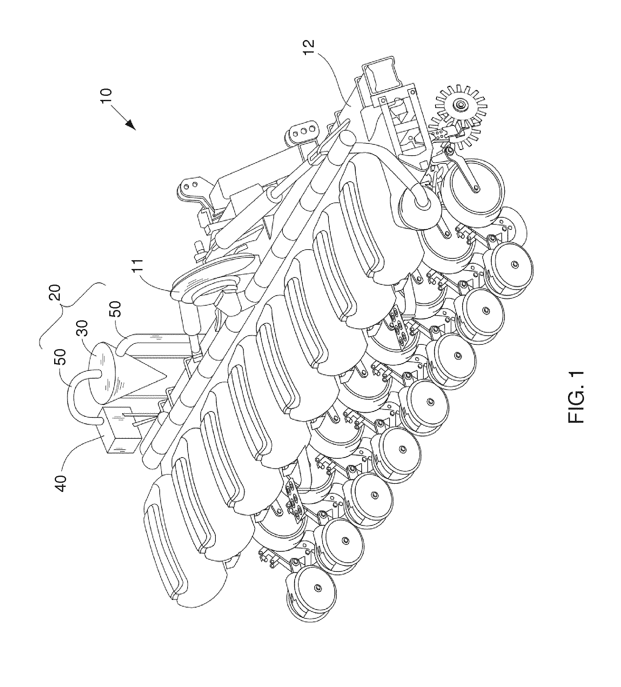
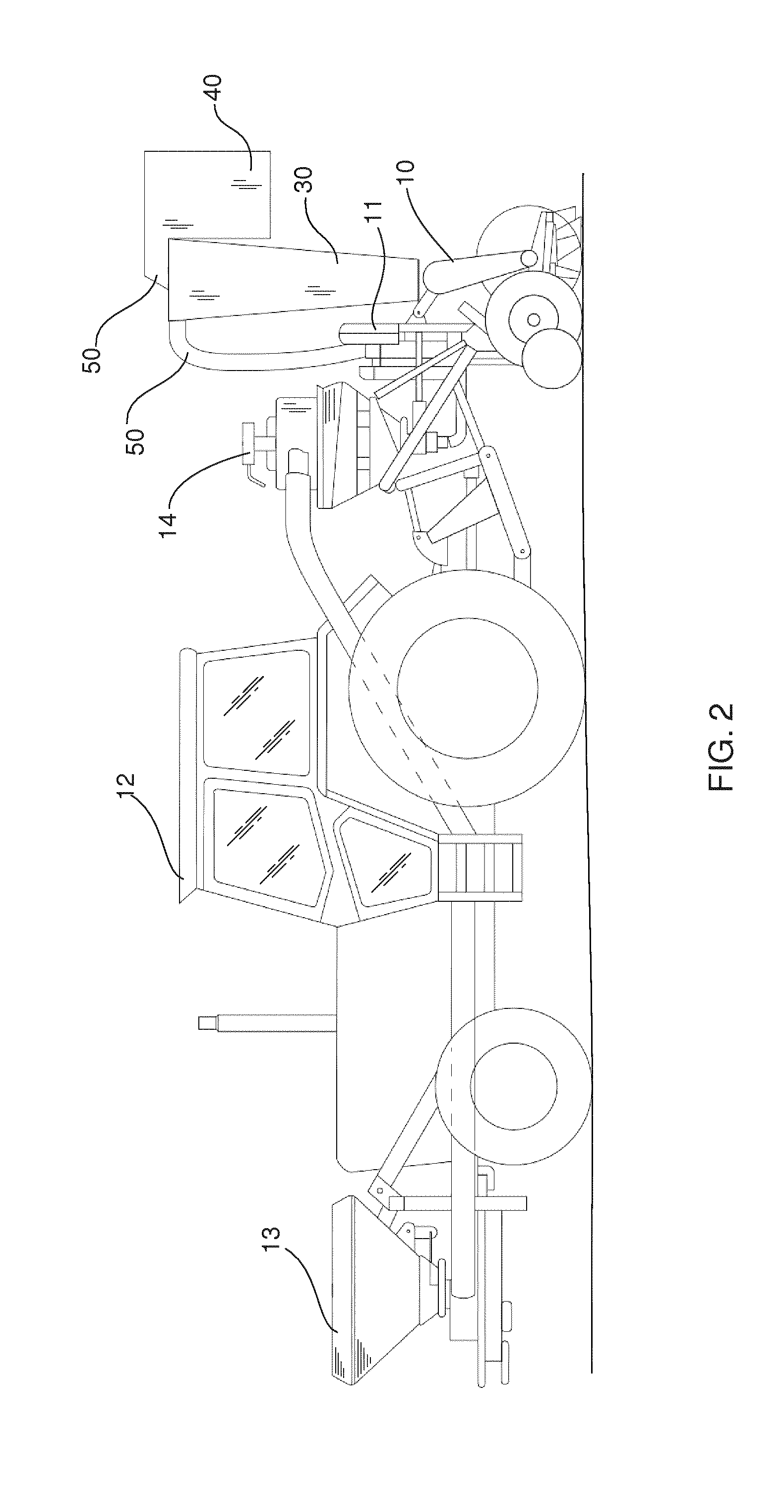
[0060]All of the exhaust air from the vacuum planter turbine was channeled to a cyclonic separator via a flexible hose. The cyclonic separator was provided in a cylindrical outer housing and having a detachable base. The cyclonic separator was fixed to the planter near the turbine and between seed hoppers.

[0061]All of the...

example 2

Evaluation of a Second Embodiment

[0067]Maize seeds were provided in a manner similar to Example 1. The cyclonic separator was provided with a length along the central axis being multiples of the width of the cyclonic separator. This was intended to result in a greater proportion of particles captured in the cyclonic separator as opposed to the filter unit. The cyclonic separator was fixed to the planter behind (referring to the direction of travel of the planter in use) the turbine and between seed hoppers. All of the exhaust air from the cyclonic separator was channeled to a filter unit via a fixed connection. The filter unit was the form of a metal housing fitted with a fine dust pocket filter (0.5 micron particle size, 820 m3 / hour maximum air flow, 2.1 m2 active filter surface area, UNIFIL AG, Switzerland). The filter unit was fixed to the cyclonic separator as a single apparatus.

[0068]In order to simulate the most demanding conditions one would expect in use, the trial was condu...

example 3

Further Evaluation of a Second Embodiment

[0071]Maize seeds were provided in a manner similar to Example 1. The cyclonic separator was provided and operated according to Example 2

[0072]A trial was conducted under dry soil conditions. A total of 23 Ha were planted and at the end of the trial the particles collected in the cyclonic separator and filter unit were weighed. Results are shown in Table 3.

TABLE 3Collected Particles (g)Collected Particles (g / Ha)TrialCyclonic SeparatorFilter UnitCyclonic SeparatorFilter Unit432841581376.6

[0073]The observation in trial 4 that the cyclonic separator gathered 95.4% of the particulate matter, and that the remaining 4.6% were caught in the filter, further demonstrated that the combination of cyclonic separator and particulate filter give an effective particulate removal process.


PUM

PropertyMeasurementUnit
Areaaaaaaaaaaa

Abstract

An exhaust air filtration apparatus comprises a vacuum planter (10) having a cyclonic separator (30) and a filter unit (40). A method of removing particulate matter can utilize the apparatus.

Description

FIELD OF THE INVENTION[0001]The present invention relates to an apparatus for the removal of particulate matter from air exhausted from vacuum seed drilling equipment, and to methods of using the apparatus.BACKGROUND OF THE INVENTION[0002]Technical progress in agriculture continues to bring advancement in planters and the seeds they sow. Towed behind a tractor, planters are machines for drilling crops such as maize (corn), soybean, sugarbeet, cotton, oil seed rape (canola) and sunflower. Planters open a sowing furrow of desired depth, drill (sow) seed into the furrow, then close the furrow covering the seed with soil. Many planters use vacuum systems whereby a fan or turbine generates a vacuum which pulls a seed toward a planting disk and holds it against a suitably-sized hole in the disk. When the disk rotates to the desired position the vacuum is released, allowing metered passage of seeds which is a component of accurate drilling. Such technology is sometimes referred to as pneum...

Claims


Application Information

Patent Timeline
IPC IPC(8): A01C7/08B01D46/52B01D45/16A01C7/04B01D50/00
CPCA01C7/081A01C7/042B01D50/002B01D45/16B01D46/521A01C7/082A01C7/04A01C7/084A01C7/166A01C7/206B01D50/20
Inventor HUSSHERR, BENOITBRANDL, FRANZ
Owner SYNGENTA PARTICIPATIONS AG
Why Eureka
Try Eureka