Supercharge Your Innovation With Domain-Expert AI Agents!

Steel plant with multiple co-rolling line and corresponding method of production

a co-rolling line and co-rolling technology, applied in the direction of metal rolling, metal rolling stands, melt-holding vessels, etc., can solve the problems of limited knowledge of combined continuous casting and rolling plants, slow-down or stoppage, and increase casting speed has a technological limit, so as to achieve high productivity

Active Publication Date: 2016-08-25
DANIELI & C OFF MEC SPA
View PDF4 Cites 7 Cited by
  • Summary
  • Abstract
  • Description
  • Claims
  • Application Information

AI Technical Summary

Benefits of technology

The present invention provides a method for producing long metal products by direct rolling of semifinished cast products, using two independent co-rolling lines. These lines are close together, which allows for high productivity and flexibility in managing the casting and rolling apparatuses. The overall width of the steel plant is minimized, resulting in cost reduction and optimized casting and rolling speeds. The invention allows for independent management of the casting lines, and different products can be produced from one line and the other, based on the needs of the plant. The invention also allows for regulation of the productivity of the two co-rolling lines, ensuring the best quality of the finished product.

Problems solved by technology

Known combined continuous casting and rolling plants can be limited in this sense, since they are unable to satisfy this requirement, and are greatly affected by stoppages, either programmed or accidental, of the rolling mill.
This limitation as above is particularly important especially in the case of steel plants with a single co-rolling line, in which any delay or problem in rolling can cause the slow-down or stoppage of the continuous casting machine upstream and, consequently, also of the whole steel works served by each steel plant.
Increasing the casting speed has a technological limit, however, determined for each continuous casting machine and for each type of product, by the fact that too high speeds penalize the castability of the semifinished cast product, even making it impossible, and also compromise the quality thereof, with consequent negative effects on the rolling process and hence on the quality of the finished product.

Method used


Image

  • Steel plant with multiple co-rolling line and corresponding method of production
  • Steel plant with multiple co-rolling line and corresponding method of production
  • Steel plant with multiple co-rolling line and corresponding method of production

Examples


Embodiment Construction

[0049]We shall now refer in detail to the various forms of embodiment of the present invention, of which one or more examples are shown in the attached drawing. Each example is supplied by way of illustration of the invention and shall not be understood as a limitation thereof. For example, the characteristics shown or described insomuch as they are part of one form of embodiment can be adopted on, or in association with, other forms of embodiment to produce another form of embodiment. It is understood that the present invention shall include all such modifications and variants.

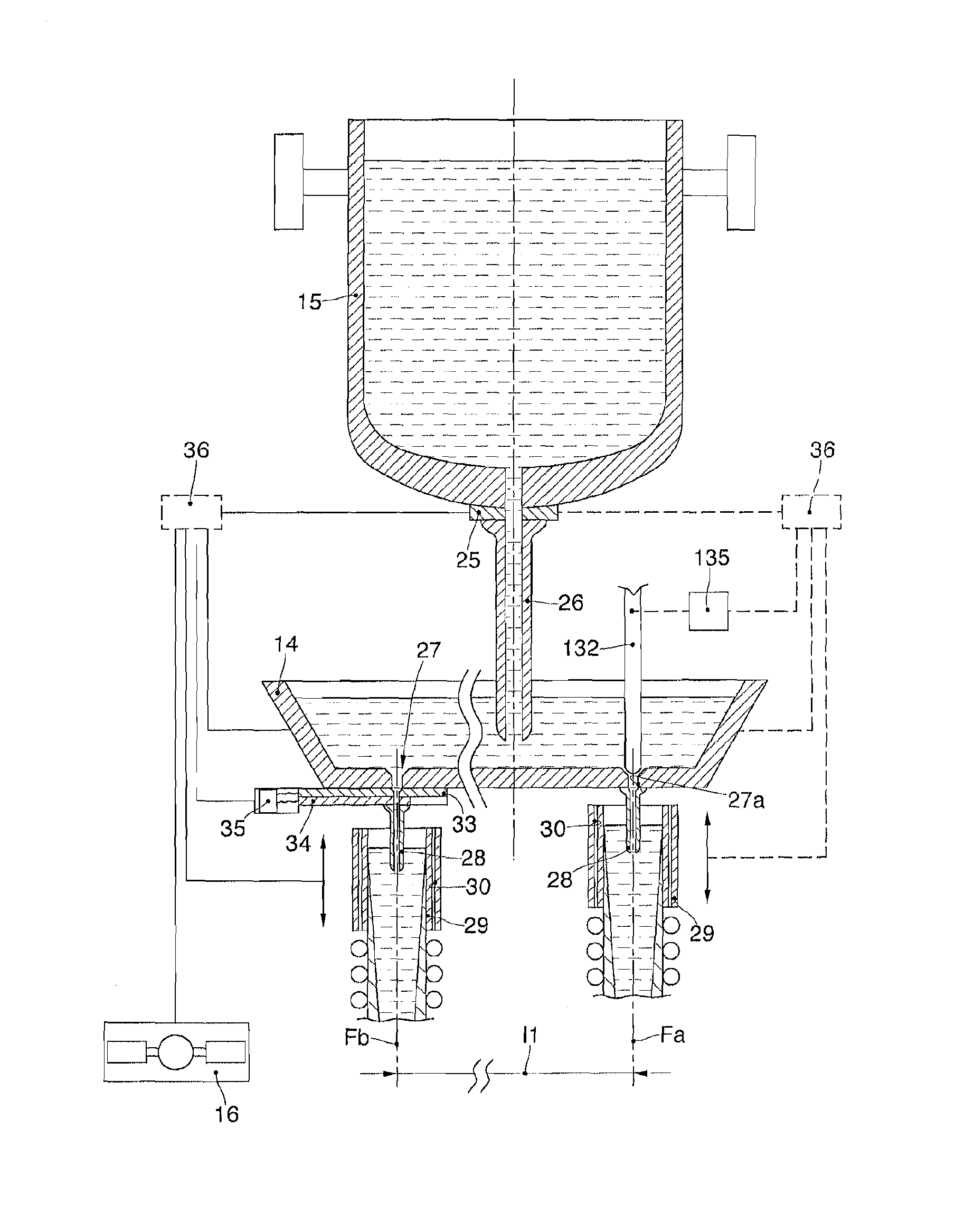
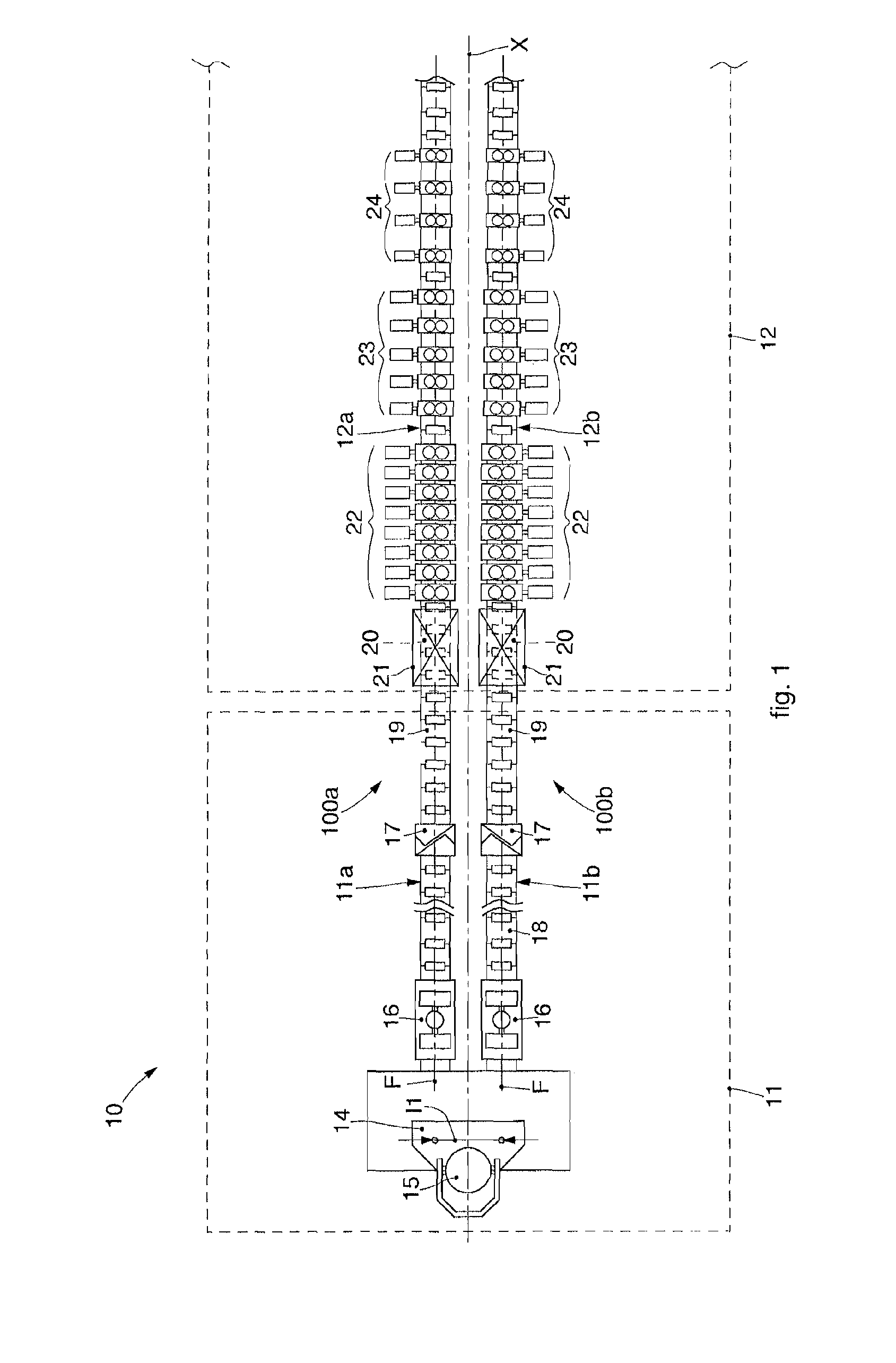
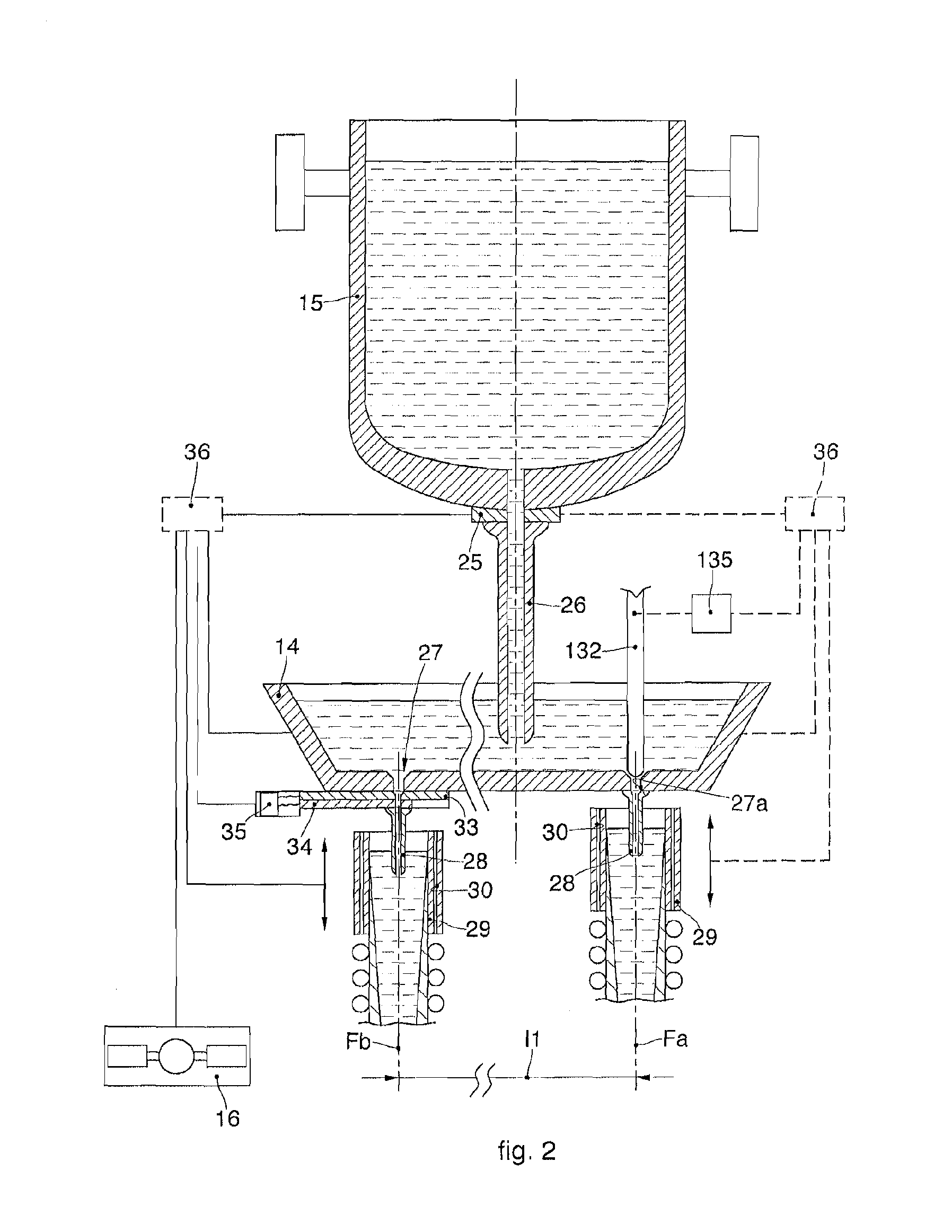
[0050]With reference to the attached drawings, a steel plant with a multiple co-rolling line for the production of long metal products according to the present invention is indicated in its entirety by the reference number 10.

[0051]According to the present description, the expression “co-rolling line” means that a casting line is aligned, that is, in axis, with respect to the respective rolling line downstrea...


PUM

PropertyMeasurementUnit
lengthaaaaaaaaaa
lengthaaaaaaaaaa
lengthaaaaaaaaaa

Abstract

A steel plant for the production of long metal products comprises a continuous casting machine and a rolling mill disposed contiguous and in direct succession downstream of the continuous casting machine. The continuous casting machine is provided with at least two casting lines and the rolling mill is provided with at least two rolling lines. The plant comprises a single feed apparatus for feeding molten metal, and the at least two casting lines are configured to receive molten metal from the single feed apparatus.

Description

FIELD OF THE INVENTION[0001]The present invention concerns a steel plant and corresponding method for making long metal products such as bars, round pieces for reinforced concrete, wire rods, beams or other profiles usable for example in mechanical or civil engineering.[0002]In particular, the present invention concerns a combined casting and rolling plant, for the direct rolling of semifinished continuous cast products according to processes defined as “endless” and “semi-endless”.BACKGROUND OF THE INVENTION[0003]It is known that long metal products, that is having a predominant longitudinal size with respect to the cross section, are normally produced by rolling long semifinished products deriving from continuous casting of the metal, for example steel.[0004]The finished products are generally bars, round pieces for reinforced concrete, rods, beams or other profiles, obtained by transforming billets or blumes, with a square, rectangular or round section.[0005]Steel plants are know...

Claims


Application Information

Patent Timeline
Patent Type & Authority Applications(United States)
IPC IPC(8): B22D11/14B22D11/103B21B1/46B22D11/041
CPCB22D11/04B22D11/103B22D11/147B21B13/22B22D11/141B21B1/466B21B2015/0014B21B1/46B22D11/041B21B1/463B22D41/08
Inventor BENEDETTI, GIANPIETROBORDIGNON, GIUSEPPEMULINARIS, FABRIZIOPOLONI, ALFREDO
Owner DANIELI & C OFF MEC SPA
Features
  • R&D
  • Intellectual Property
  • Life Sciences
  • Materials
  • Tech Scout
  • Unparalleled Data Quality
  • Higher Quality Content
  • 60% Fewer Hallucinations
Learn More