
Turbocharger diffuser center body

Active Publication Date: 2016-08-25
GARRETT TRANSPORATION I INC
View PDF7 Cites 13 Cited by
  • Summary
  • Abstract
  • Description
  • Claims
  • Application Information

AI Technical Summary

Benefits of technology

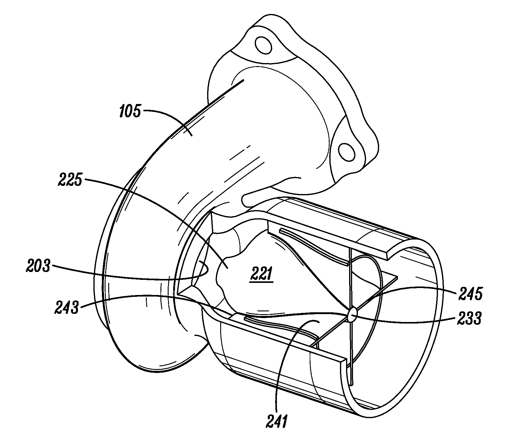
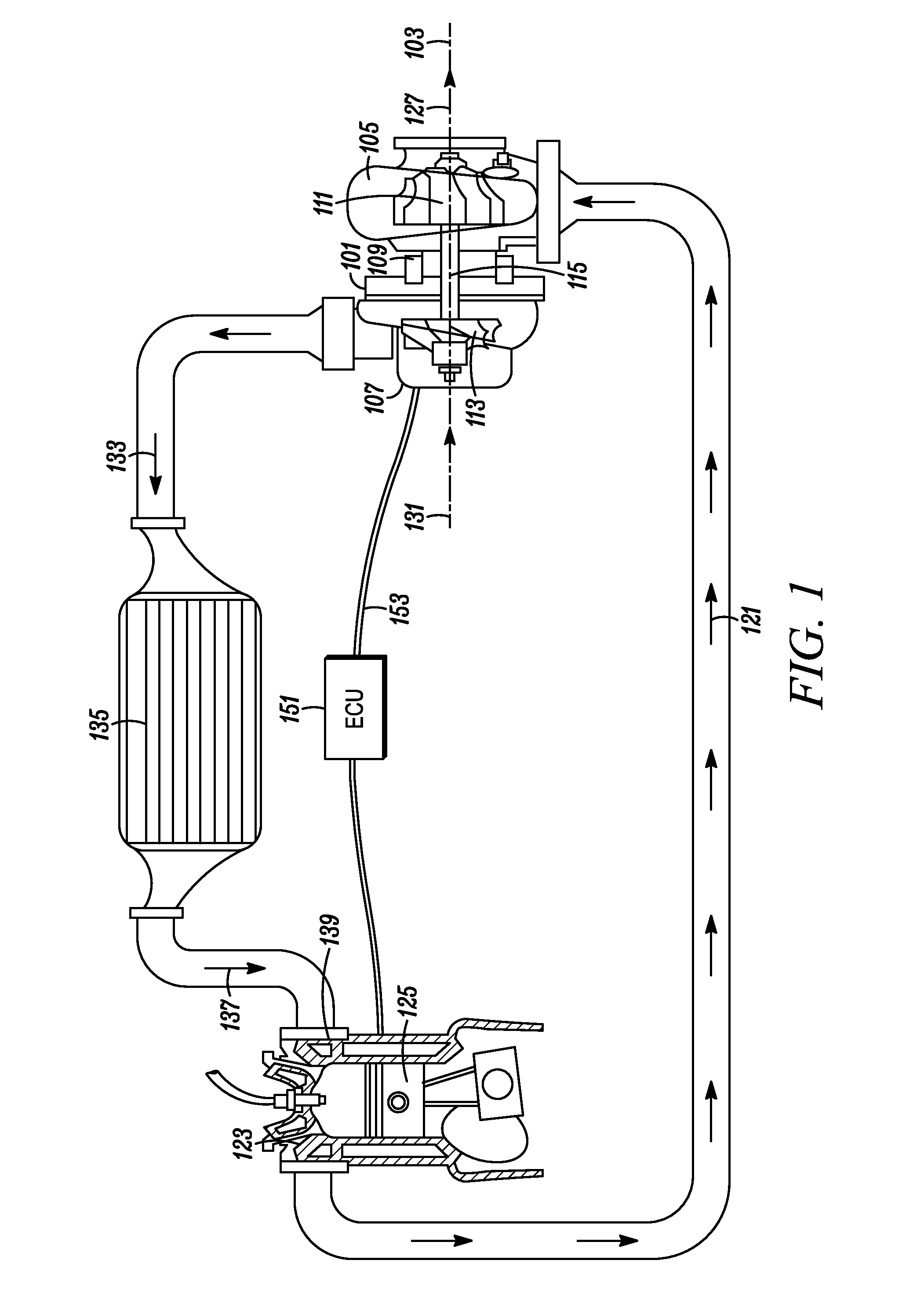
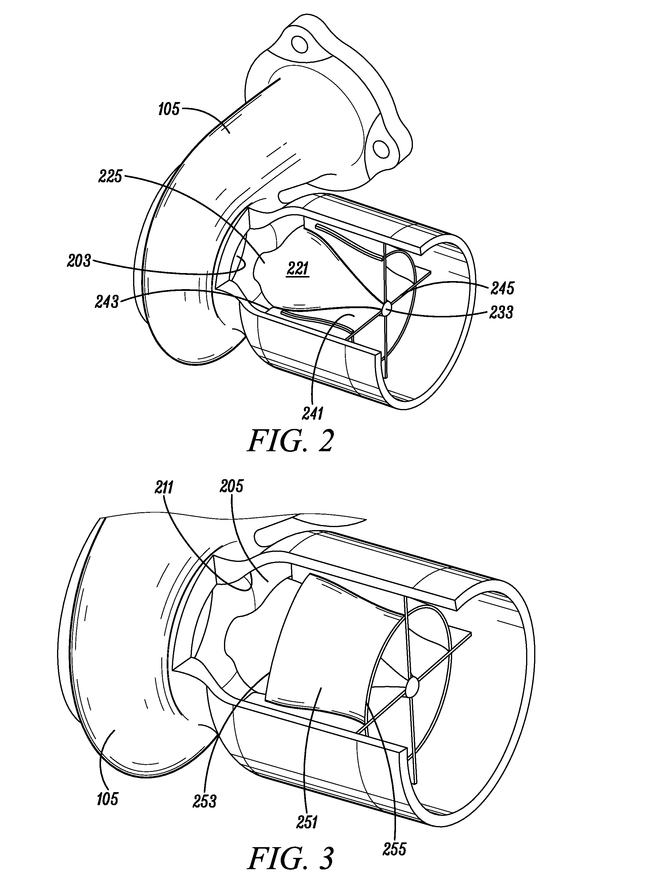
The present invention provides a compact automottic turbocharger turbine diffuser that is highly efficient in reducing the kinetic energy of an exhaust gas stream. The turbine features a center body and de-swirl vanes that support the center body and a trailing edge of the de-swirl vanes that prevents free vortex flow. The turbine also features annular-type guide vanes and a wastegate system that improves the diffusing flow in the rear section of the diffuser. These features reduce efficiency losses across the off design operating range of the turbine, particularly under transient conditions.

Problems solved by technology

These off design operating conditions occur frequently in turbocharger turbine operation due to pulsing inlet flow conditions, size constraints (e.g., a turbine diameter smaller than optimum), and conditions where variable nozzle guide vanes (in the turbine inlet) are operated away from their nominal position.
These off design operating conditions result in a very low blade speed ratio condition for the turbine stage which results in a high degree of exit swirl.
This tangential velocity portion increases the total kinetic energy of the exhaust stream over that of just the axial velocity portion, and thereby causes efficiency losses across the off design operating range of the turbine, particularly under transient conditions.
It should be noted that any effort to deal with this problem is constrained by size limitations for the turbocharger, i.e., package constraints.
This is particularly true for automotive turbochargers, which typically have significant size limitations.
Nevertheless, applying a traditional conical diffuser design to a swirling flow with package constraints typically results in significant separation of the flow and inefficient diffusion.
De-swirl vanes with their leading edge angle matched to the flow swirl angle can be used in attempt to manage the problem, but these only operate effectively at a small range of operating conditions because the swirl angle of the flow into the diffuser varies dramatically across the useful operating range of the turbine.
Thus, the use of de-swirl vanes results in high (angle of) incidence losses into the de-swirl vanes at operating conditions that are not close to the operating conditions for which the vanes were designed.

Method used


Image

  • Turbocharger diffuser center body
  • Turbocharger diffuser center body
  • Turbocharger diffuser center body

Examples


Embodiment Construction

[0021]The invention summarized above and defined by the enumerated claims may be better understood by referring to the following detailed description, which should be read with the accompanying drawings. This detailed description of particular preferred embodiments of the invention, set out below to enable one to build and use particular implementations of the invention, is not intended to limit the enumerated claims, but rather, it is intended to provide particular examples of them.

[0022]Typical embodiments of the present invention utilize an increase in the mean diameter of an exhaust gas stream (i.e., of flow) directly after the turbine wheel exit to reduce the swirl angle of the flow. This provides for axial or close-to-axial de-swirl vanes to be used through the remainder of the diffuser without significant angle of incidence losses over a wide range of operating conditions. In this way, effective diffusion can be managed over a wide range of inlet swirl angles, and therefore a...


PUM


Abstract

A turbocharger turbine having housing walls defining a diffuser. Within the diffuser, a center body within the diffuser is supported by de-swirl vanes extending from the diffuser wall. The center body forms a de-swirl passageway having an increasing mean diameter of flow from an upstream end of the center body to a leading edge of the de-swirl vanes. A trailing edge of the de-swirl vanes is near the downstream end of the center body. Annular-type guide vanes surround the center body within the de-swirl passageway. A wastegate system is configured to vent wastegate flow into the diffuser through injection ports on the de-swirl vanes, annular guide vanes and / or center body.

Description

[0001]The present invention relates generally to turbocharger turbines, and more particularly, to an exhaust gas diffuser configuration for a radial automotive turbocharger turbine.BACKGROUND OF THE INVENTION[0002]Radial turbocharger turbines are provided with diffusers extending axially downstream from a turbine wheel around a wheel centerline. The diffuser is configured to reduce airflow velocity. To accomplish this, the cross-sectional area of the diffuser increases from an upstream end of the diffuser to the downstream end of the diffuser. Because the mass flow rate through the diffuser is constant, this increased cross-sectional area provides for decreased velocity, decreased dynamic pressure, and increased static pressure.[0003]Turbines are designed for optimal operation at a design operating condition. At this operating condition, an exhaust gas stream will enter the diffuser having substantially axial flow. Nevertheless, at so called ‘off design’ operating conditions (i.e., ...

Claims


Application Information

Patent Timeline
IPC IPC(8): F01D25/24F01D5/02F02B33/40F01D9/04F02B37/00
CPCF01D25/24F01D9/041F02B37/00F02B33/40F01D5/02F05D2220/40F05D2250/324F05D2240/14F05D2240/24F01D9/02F01D17/105F01D25/30F02B37/18F05D2240/12Y02T10/12
Inventor WILKINS, CHRISTOPHER W.MAGALHAES, WAGNER M.SUGUMARAN, BHARATHI RAJABABAK, MARTIN
Owner GARRETT TRANSPORATION I INC
Learn More