Pre-combustion-chamber type gas engine

a gas engine and combustion chamber technology, applied in the direction of engines, machines/engines, mechanical equipment, etc., can solve the problems of difficult flame-propagating combustion and inability to improve combustion efficiency, so as to reduce the excessive supply of ignition fuel gas, prolong the time of ignition fuel gas stay, and improve combustion efficiency

Active Publication Date: 2016-08-25
MITSUBISHI HEAVY IND ENGINE & TURBOCHARGER LTD
View PDF0 Cites 34 Cited by
  • Summary
  • Abstract
  • Description
  • Claims
  • Application Information

AI Technical Summary

Benefits of technology

[0038]According to at least one embodiment of the present invention, it is possible to extend the time the ignition fuel gas stays in the pre-combustion chamber by providing the opening of the gas supply channel for the pre-combustion chamber on the

Problems solved by technology

However, if lean-premix combustion is to be performed, or if a bore diameter is large (e.g. approximately 150 mm), it may be difficult to

Method used


Image

  • Pre-combustion-chamber type gas engine
  • Pre-combustion-chamber type gas engine
  • Pre-combustion-chamber type gas engine

Examples


first embodiment

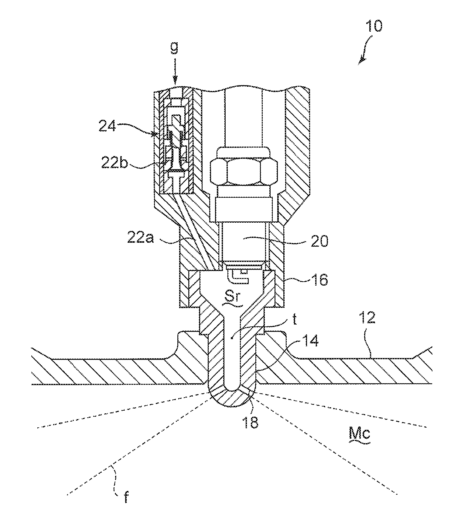
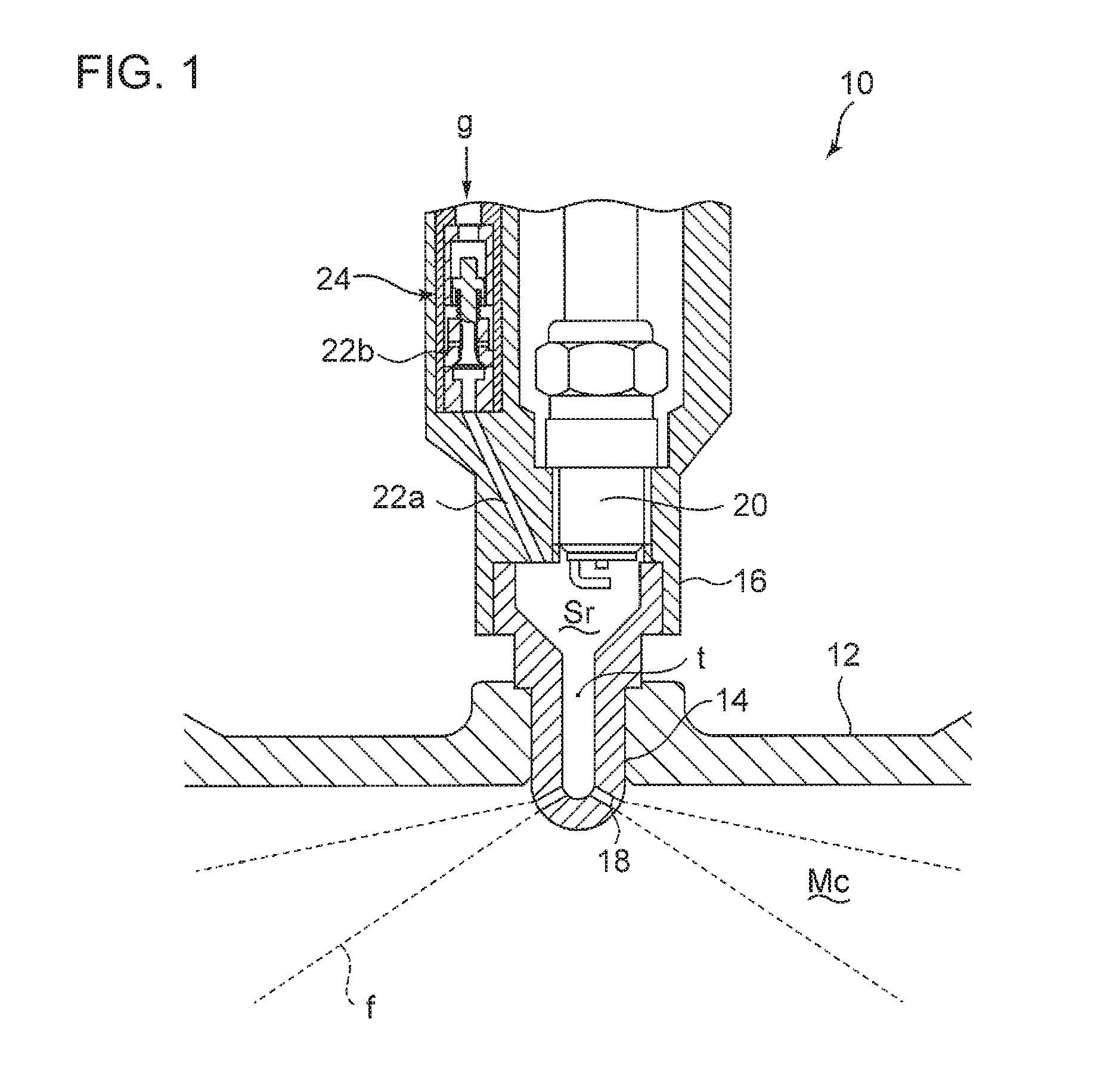
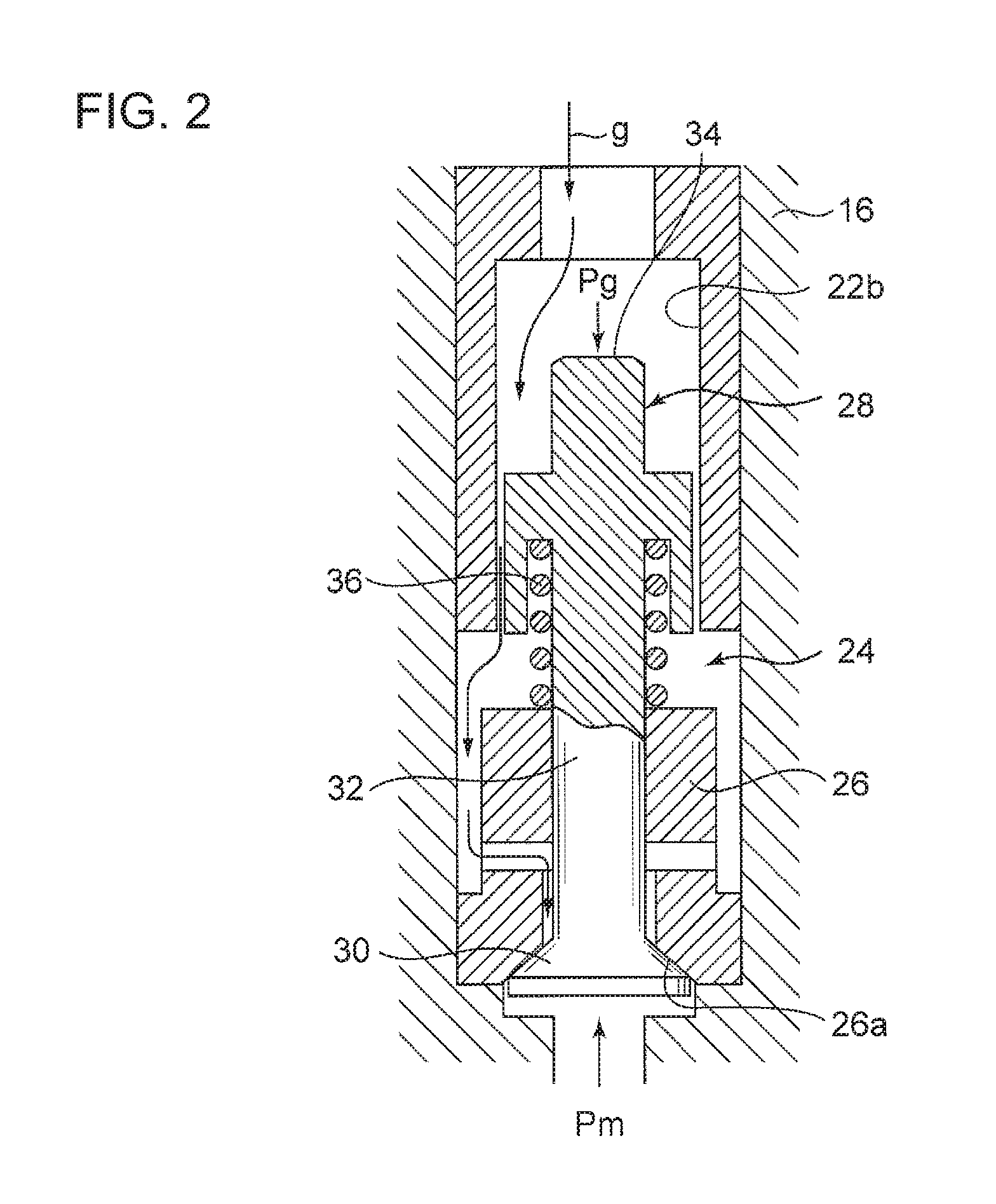
[0057]A pre-combustion-chamber type gas engine according to the first embodiment of the present invention will be described with reference to FIGS. 1 to 5. FIG. 1 is a diagram of a cylinder head portion 10 of a pre-combustion-chamber type gas engine according to the present embodiment. A main combustion chamber Mc is formed inside a cylinder 12. A pre-combustion chamber Sr is formed by a pre-combustion-chamber member 14 of a hollow cylindrical shape having an outer diameter varied in a longitudinal axial direction, and a cover member 16 disposed so as to cover an upper opening of the pre-combustion-chamber member 14. The pre-combustion-chamber member 14 is fixed by press fitting in a fitting hole formed in the middle of an upper part of the cylinder 12. A large-diameter section having a large inner diameter at an upper part is formed inside the pre-combustion-chamber member 14, and a throat section “t” of a cylindrical shape having an inner diameter smaller than that of the large-di...

second embodiment

[0071]Next, the second embodiment of the present invention will be described with reference to FIGS. 7 and 8. The present embodiment is an example in which a space for forming a gas supply channel for pre-combustion chamber can be secured at the side of the pre-combustion chamber Sr. In the present embodiment, a gas supply channel 40 for pre-combustion chamber (gas supply tube for pre-combustion chamber) for supplying the ignition fuel gas “g” to the pre-combustion chamber Sr is disposed on the side of the pre-combustion-chamber member 14. The gas supply channel 40 for pre-combustion chamber is attached substantially in the horizontal direction to an upper end section of the pre-combustion chamber Sr, which is an upper end section of the large diameter section of the pre-combustion chamber Sr. Specifically, in the present embodiment, the gas supply channel for pre-combustion chamber has an opening on an upper part of a side wall of a partition wall forming the pre-combustion chamber...

third embodiment

[0075]Next, the third embodiment of the present invention will be described with reference to FIGS. 9 and 11. In the present embodiment, similarly to the first embodiment, the gas supply channels 22a and 22b for pre-combustion chamber are disposed inside the cover member 16 disposed on an upper part of the pre-combustion-chamber member 14 so as to extend to an upper end of the pre-combustion-chamber member 14.

[0076]As illustrated in FIG. 9, the cover member 16 connects to a pocket portion 50 formed on the upper end of the pre-combustion-chamber member 14.

[0077]As illustrated in FIGS. 10 and 11, the pocket portion 50 includes an upper surface 50a and a bottom surface 50b, which are substantially horizontal, and a side surface 50c of a semi-cylindrical shape. The upper surface 50a is formed by a lower surface of the cover member 16. The gas supply channel 22a for pre-combustion chamber has an opening on an outer end section of the upper surface 50a. A hole 52 with a linear axis is for...


PUM


Abstract

An object is to improve a trap effect to trap ignition fuel gas supplied to a pre-combustion chamber and reduce an amount of non-combusted ignition fuel gas flowing out of the pre-combustion chamber to suppress a decrease in combustion efficiency. A pre-combustion-chamber type gas engine includes: a pre-combustion chamber Sr disposed on a cylinder head portion 10; a spark plug 20 disposed on an upper part of the pre-combustion chamber Sr; a pre-combustion-chamber gas supply mechanism configured to supply ignition fuel gas “g” to the pre-combustion chamber Sr via gas supply channels for the pre-combustion chamber 22a and 22b with an opening on an upper part of the pre-combustion chamber Sr; and a check valve 24 disposed in the gas supply channel 22b for the pre-combustion chamber. The opening of the gas supply channel 22a for the pre-combustion chamber is disposed on a lower surface of a cover member 16 forming the pre-combustion chamber Sr or on an upper section of a side wall of a pre-combustion-chamber member 14, the opening facing in a tangent direction of a side-wall inner peripheral surface 14a of the pre-combustion-chamber member 14. The ignition fuel gas “g” supplied to the pre-combustion chamber Sr forms a swirl flow s1 which swirls about a longitudinal axis x of the pre-combustion chamber Sr inside the pre-combustion chamber Sr.

Description

TECHNICAL FIELD[0001]The present disclosure relates to a pre-combustion-chamber type gas engine which performs spark ignition inside a pre-combustion chamber.BACKGROUND ART[0002]A common gas engine includes a spark plug disposed inside a combustion chamber, and flame-propagating combustion is performed starting from ignition of fuel gas by the spark plug. However, if lean-premix combustion is to be performed, or if a bore diameter is large (e.g. approximately 150 mm), it may be difficult to perform flame-propagating combustion in a limited time by ignition using a spark plug, and thus combustion efficiency may not be improved.[0003]As a countermeasure to the above, a plurality of plugs may be provided, or a pre-combustion-chamber type gas engine may be employed.[0004]A pre-combustion-chamber type gas engine is used for a gas engine which has a large bore diameter and which performs lean-premix combustion. The combustion process of the pre-combustion-chamber type gas engine is as fol...

Claims


Application Information

Patent Timeline
IPC IPC(8): F02B19/08F02B43/04F02B19/12
CPCF02B19/08F02B19/12F02B19/108F02B43/04F02M21/0275Y02T10/125Y02T10/32F02M21/0242F02B19/18F02M21/02F02M21/0248F02M21/0281Y02T10/12Y02T10/30
Inventor YUUKI, AKIHIROTAKEMOTO, DAISUKEFURUKAWA, YUTA
Owner MITSUBISHI HEAVY IND ENGINE & TURBOCHARGER LTD
Why Eureka
Try Eureka