
Diagnosis device

a diagnostic device and a technology for detecting the position of the exhaust gas, applied in the direction of instruments, machines/engines, mechanical equipment, etc., can solve the problem that the regulation value of the exhaust gas cannot be satisfied, and achieve the effect of higher accuracy

Inactive Publication Date: 2016-08-25
ISUZU MOTORS LTD
View PDF3 Cites 6 Cited by
  • Summary
  • Abstract
  • Description
  • Claims
  • Application Information

AI Technical Summary

Benefits of technology

The device in this patent aims to better identify when the DPF (Diesel Particulate Filter) is failing.

Problems solved by technology

When a PM collection capability of the DPF is deteriorated due to the breakage or the like, the PM, which is not collected by the DPF and is slipped through the DPF, is emitted in an atmospheric air, so that it is possible that an exhaust gas regulation value cannot be satisfied.

Method used


Image

  • Diagnosis device
  • Diagnosis device
  • Diagnosis device

Examples


Embodiment Construction

[0019]Hereinafter, a diagnosis device according to an embodiment of the present invention will be described with reference to accompanying drawings. Identical parts are given identical reference numerals and symbols, and their names and functions are identical as well. Therefore, detailed description of such parts will not be repeated.

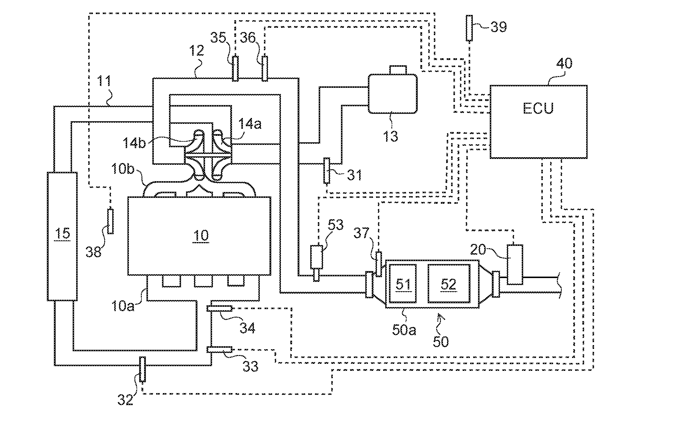
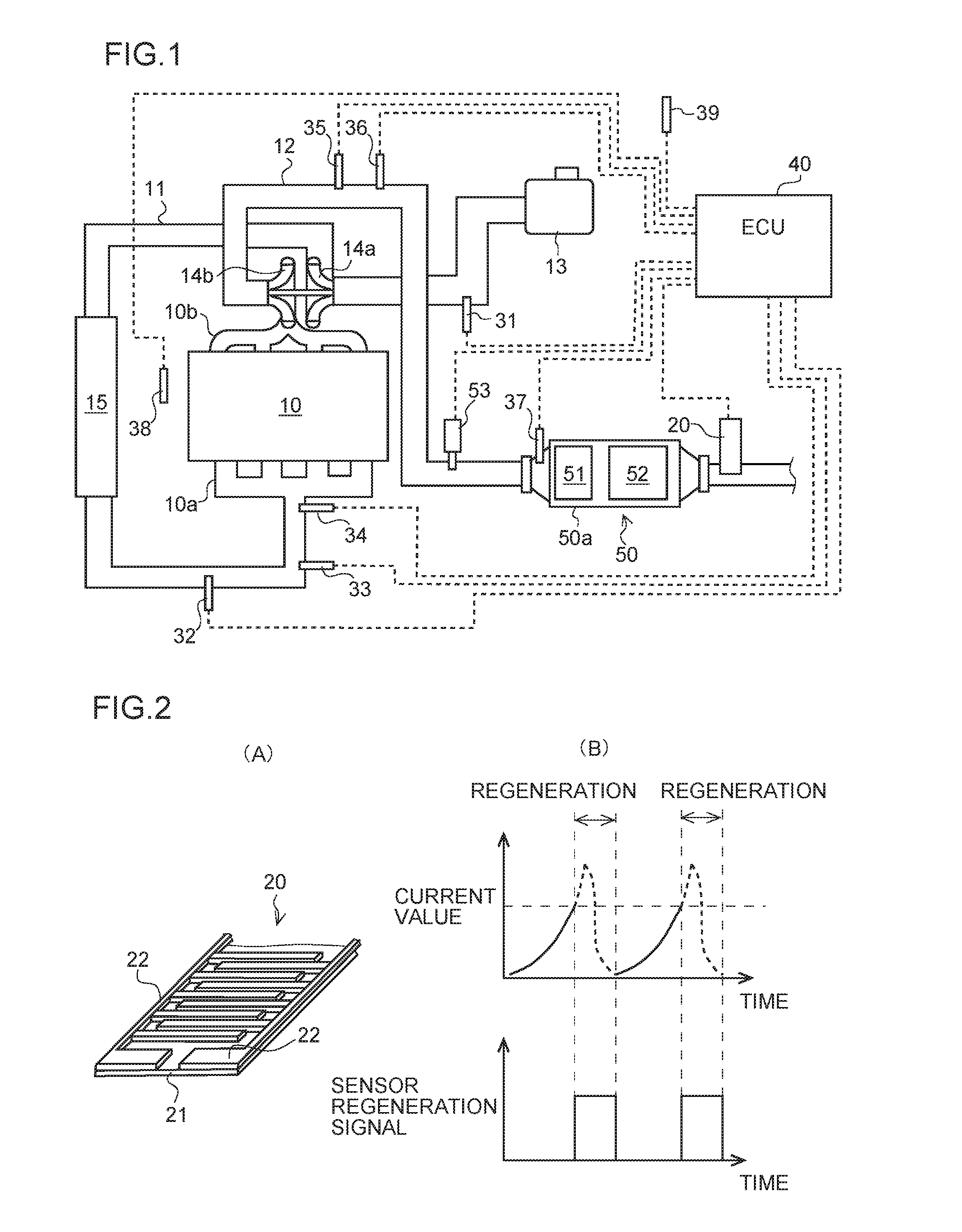
[0020]As illustrated in FIG. 1, a diesel engine (hereinafter simply referred to as “engine”) 10 is provided with an intake manifold 10a and an exhaust manifold 10b. The intake manifold 10a is connected to an intake passage 11 for introducing fresh air, and the exhaust manifold 10b is connected to an exhaust passage 12 for emitting an exhaust gas to the atmospheric air.

[0021]The intake passage 11 is provided with, in turn from the intake upstream side, an air cleaner 13, a MAF sensor 31, a compressor of a turbo charger 14a, an intercooler 15, an intake temperature sensor 32, an intake oxygen concentration sensor 33, a boost pressure sensor 34 and the li...


PUM


Abstract

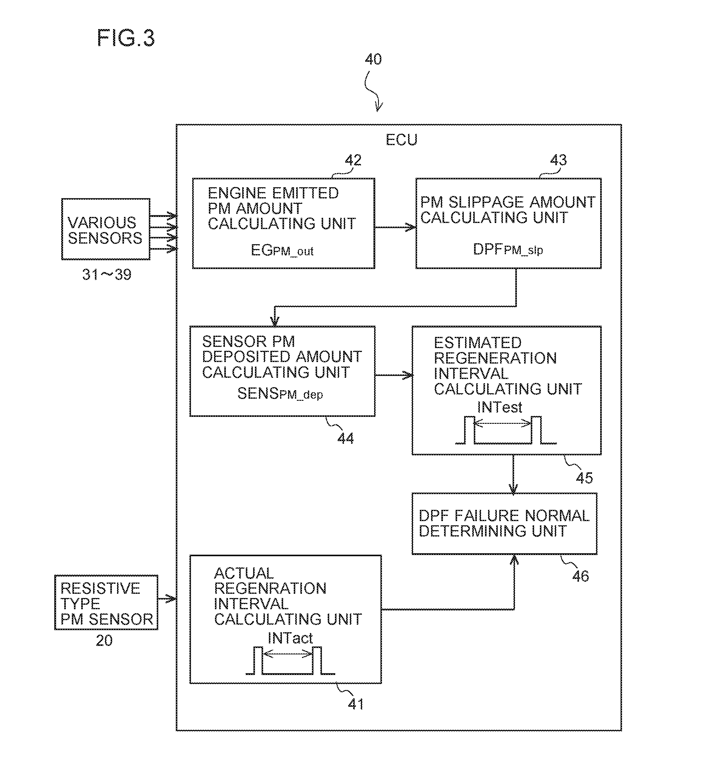
A diagnosis device includes: a diesel particulate filter (DPF) collecting particulate matter (PM) in exhaust gas; a resistive type PM sensor provided downstream of the DPF, detecting an amount of PM from current flowing through PM deposited between electrodes. An actual regeneration interval calculator calculating an actual interval from completion of regeneration of the sensor to a start of the next regeneration; a PM slippage amount calculator estimating an amount of PM slippage in exhaust gas that slips through the DPF, assuming the DPF is normal; an estimated regeneration interval calculator calculating, on the basis of the PM slippage amount, an estimated interval from completion of the regeneration of the sensor to the start of the next regeneration; and a DPF failure-normal determination device determining whether the DPF has failed or is normal by comparing the actual interval to the estimated interval.

Description

TECHNICAL FIELD[0001]The present invention relates to a diagnosis device, and more particularly, relates to a failure diagnosis of an exhaust gas purification filter provided in an exhaust system of an internal combustion engine.BACKGROUND ART[0002]As an exhaust gas purification filter provided in an exhaust system such as a diesel engine, a Diesel Particulate Filter (DPF) has been known that collects a Particulate Matter (PM) such as soot or the like contained in an exhaust gas.[0003]When a PM collection capability of the DPF is deteriorated due to the breakage or the like, the PM, which is not collected by the DPF and is slipped through the DPF, is emitted in an atmospheric air, so that it is possible that an exhaust gas regulation value cannot be satisfied. For this reason, there is a demand to perform an on-board diagnosis of the failure of the DPF.[0004]As a technique for determining the failure of the DPF, for example, there is known a method in which a resistive type PM senso...

Claims


Application Information

Patent Timeline
IPC IPC(8): G01M15/10F01N11/00
CPCF01N11/00F01N2550/04G01M15/102Y02T10/47F01N2560/05F01N2900/0408F01N2900/0416F01N2900/0418F01N2900/0422Y02T10/40
Inventor HANAWA, SATOSHIUCHIYAMA, TADASHIFUJIE, HIDEKAZUNAKADA, TERUOMURASAWA, NAOTO
Owner ISUZU MOTORS LTD
Learn More