Display apparatus, display method, and program

a display method and display apparatus technology, applied in the field of display apparatus, can solve the problems of difficult patient concentration on training, inability to effectively train, and paralysis of limbs in some cases, and achieve the effect of efficient training

Active Publication Date: 2016-08-25
SEIKO EPSON CORP
View PDF4 Cites 12 Cited by
  • Summary
  • Abstract
  • Description
  • Claims
  • Application Information

AI Technical Summary

Benefits of technology

[0037]According to this application example, the display apparatus includes a recorded motion image output section and a light-transmissive head-mounted display. Recorded motion images are displayed in one of the first display section and the second display section. The other display section allows a patient to view a body part of the patient through a motion image display section. The patient can therefore move a paralyzed body part by following the recorded motion images as guidance and check the motion of the paralyzed body part. Therefore, since the patient can simultaneously view the guidance and the action of the patient's own body part, the patient can conduct the training while checking an effect of the training. As a result, the training can be efficiently conducted.

Problems solved by technology

When the neural circuit in the brain is damaged due to a stroke, limbs are paralyzed in some cases.
When animation images are used, they are images different from an actual body part and make it difficult for the patient to concentrate on training.
Further, when the method does not fit the patient, the training is unlikely to be effective.

Method used


Image

  • Display apparatus, display method, and program
  • Display apparatus, display method, and program
  • Display apparatus, display method, and program

Examples


first embodiment

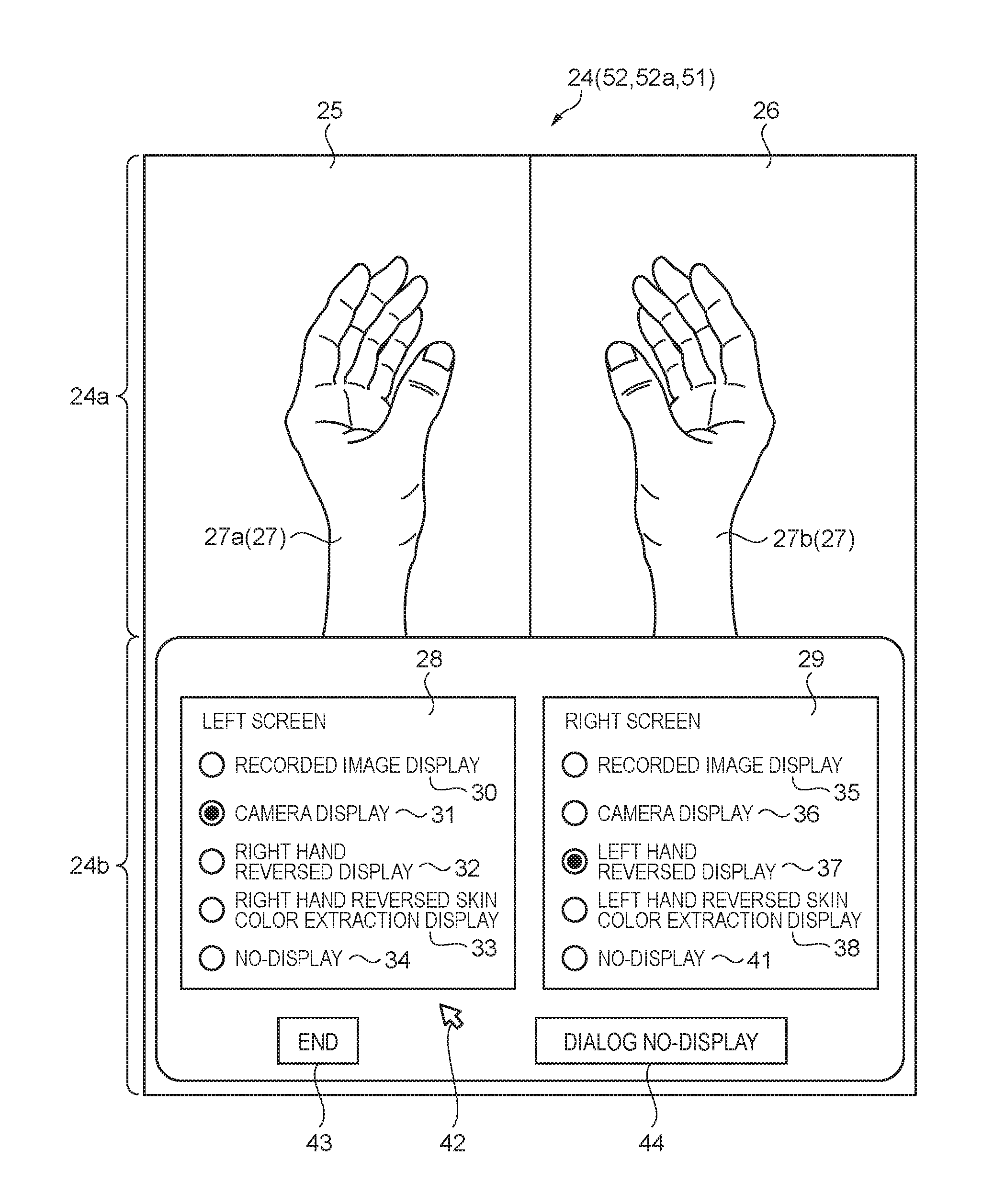
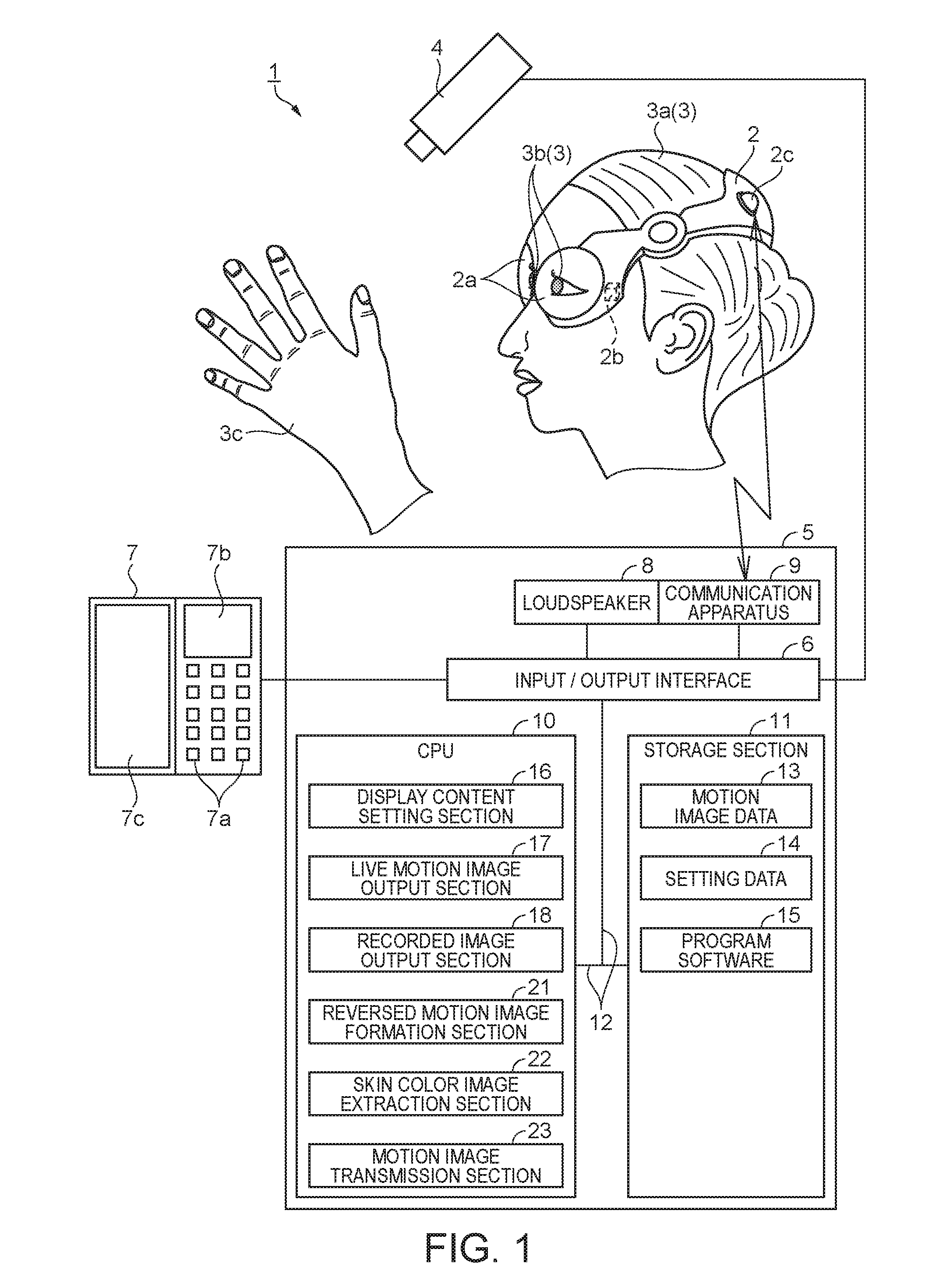
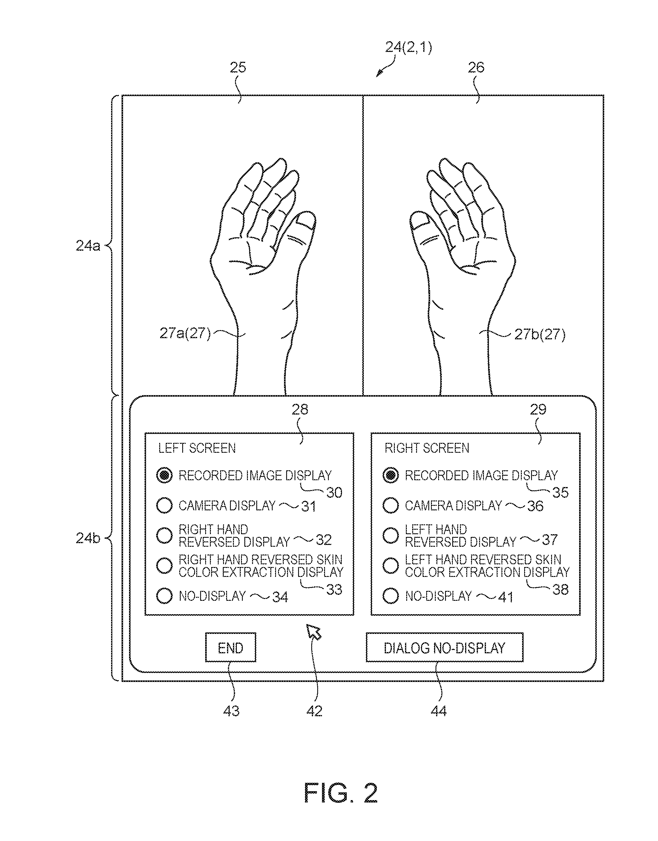
[0052]A rehabilitation assistance apparatus according to a first embodiment will be described with reference to FIGS. 1 and 2. FIG. 1 is a block diagram showing the configuration of the rehabilitation assistance apparatus. A rehabilitation assistance apparatus 1 as a display apparatus includes a head-mounted display 2 as a motion image display section and a light transmissive head-mounted display, and the head-mounted display 2 is mounted on a head 3a of a patient 3, as shown in FIG. 1. The head-mounted display 2 has mirror sections 2a so located as to face eyes 3b of the patient 3. The head-mounted display 2 includes projection sections 2b, and the projection sections 2b output light toward the mirror sections 2a. The light is reflected off the mirror sections 2a and incident on the eyes 3b. The patient 3 can view virtual motion images on the basis of the light incident on the eyes 3b. The head-mounted display 2 allows the right eye and the left eye to see motion images different f...

second embodiment

[0097]An embodiment of the rehabilitation assistance apparatus will next be described with reference to a block diagram showing the configuration of a rehabilitation assistance apparatus shown in FIG. 7. The present embodiment differs from the first embodiment in that the head-mounted display 2 is provided with a camera. The same points as those in the first embodiment will not be described.

[0098]That is, in a rehabilitation assistance apparatus 46 of the present embodiment, the head-mounted display 2 is provided with a camera 47, as shown in FIG. 7. Live motion images captured with the camera 47 are transmitted by the communication section 2c to the communication apparatus 9. The camera 47 has the same function as that of the camera 4 in the first embodiment.

[0099]Since the head-mounted display 2 is provided with the camera 47, motion images captured with the camera 47 are synchronized with motion of the head 3a of the patient 3. The direction in which the camera 47 captures motion...

third embodiment

[0100]An embodiment of the rehabilitation assistance apparatus will next be described with reference to FIGS. 8 to 11. FIG. 8 is a block diagram showing the configuration of the rehabilitation assistance apparatus. FIGS. 9 to 11 are diagrammatic views for describing a rehabilitation method. The present embodiment differs from the first embodiment in that the head-mounted display 2 is replaced with a panel-shaped display. The same points as those in the first embodiment will not be described.

[0101]That is, in the present embodiment, a rehabilitation assistance apparatus 51 includes a display 52, as shown in FIG. 8. The display 52 includes a display section 52a, a stand 52b, and a communication section 52c. The display 52 can be a liquid crystal display, an organic electroluminescence display, a plasma display, a field emission display, or any other display. The display 52 is preferably capable of color representation because color representation allows representation closer to the ac...


PUM

PropertyMeasurementUnit
skin coloraaaaaaaaaa
coloraaaaaaaaaa
magnetic fieldaaaaaaaaaa

Abstract

A display apparatus includes a camera that outputs live motion images, a recorded motion image output section that outputs recorded motion images produced, a reversed motion image formation section that forms reversed motion images produced by reversing the live motion images, a skin color image extraction section that extracts images having a skin color from the live motion images and reverses the extracted images to form skin color reversed motion images, a motion image display section having a first display section and a second display section, and a display content setting section that sets display contents that are contents to be displayed in the first display section and the second display section, and the display content setting section selects contents to be displayed motion image display section from the live motion images, the recorded motion images, the reversed motion images, and the skin color reversed motion images.

Description

BACKGROUND[0001]1. Technical Field[0002]The present invention relates to a display apparatus, a display method, and a program.[0003]2. Related Art[0004]When the neural circuit in the brain is damaged due to a stroke, limbs are paralyzed in some cases. Methods that allow such a patient to undergo rehabilitation have been invented. One of the methods causes the patient to think that the patient should attempt moving a paralyzed limb and shows the patient images in which the paralyzed limb is moving so that the patient has a feeling as if the limb were moving.[0005]A patient whose limb has been lost due, for example, to an accident sometimes has a painful sensation in the limb. The phenomenon is called a phantom pain. A method similar to the method described above has been proved to be effective for such a patient. In the method, an image that causes the patient to have a feeling as if the lost limb existed is shown to the patient. The method allows appropriate recognition of the lost ...

Claims


Application Information

Patent Timeline
Patent Type & Authority Applications(United States)
IPC IPC(8): H04N5/765G06K9/46G02B27/01G11B27/031G06T7/20G06T7/40G06T7/00
CPCH04N5/765G06T7/408G06K9/4652G06T2207/30088G11B27/031G06T7/20G02B27/017G06T7/0012G02B2027/0187G11B27/34G16H20/30H04N5/77
Inventor KITAZAWA, TAKAYUKITANAKA, HIDEKIMARUYAMA, YUYA
Owner SEIKO EPSON CORP
Why Eureka
Try Eureka